Honda Pilot: A/T System Description - Power Flow
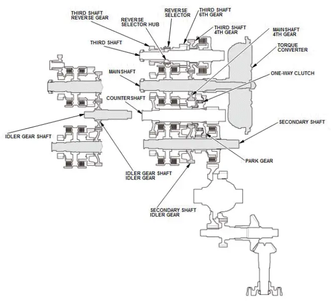
P Position
Hydraulic pressure is not applied to the clutches; power is not transmitted to the countershaft. The countershaft is locked by the park pawl interlocking the park gear on the countershaft.
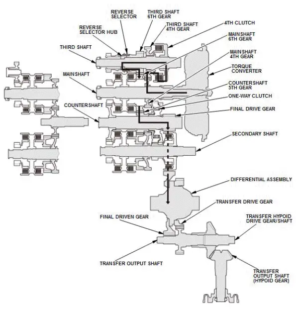
N Position
Engine output transmitted from the mainshaft drives the mainshaft 4th gear, the third shaft 4th gear, the idler gear shaft idler gear, and the secondary shaft idler gear, but since hydraulic pressure is not applied to the clutches, output is not transmitted to the countershaft.
In this position, the position of the reverse selector differs according to whether the shift lever shifted from D or R:
- When shifted from D, the reverse selector engages with the third shaft 6th gear and the reverse selector hub, and the 6th gear engages with the third shaft.
- When shifted from R, the reverse selector engages with the third shaft reverse gear and the reverse selector hub, and the reverse gear engages with the third shaft.
NOTE: This illustration shows the AWD transfer assembly that is not available on all models.
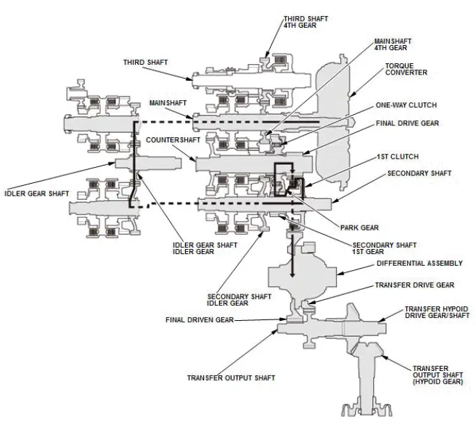
D Position, D4 driving mode and L with Automatic Shift Mode
In D, D4 driving mode, and L the optimum gear is automatically selected from 1st, 2nd, 3rd, 4th, 5th, and 6th gears in D; 1st, 2nd, 3rd, and 4th gears in D4 driving mode; and 1st, and 2nd gears in L according to conditions between the accelerator pedal command or position (engine loading) and the vehicle speed.
In 1st gear
- Hydraulic pressure is applied to the 1st clutch, then the 1st clutch engages the secondary shaft 1st gear with the secondary shaft.
- Mainshaft rotation is transmitted to the mainshaft 4th gear splined with the mainshaft.
- The mainshaft 4th gear drives the secondary shaft idler gear splined with the secondary shaft and the secondary shaft via the idler gear shaft idler gear.
- The secondary shaft and the secondary shaft 1st gear engaged by the 1st clutch, and the secondary shaft 1st gear drives the countershaft 1st gear.
- The countershaft 1st gear drives the park gear splined with the countershaft via the one-way clutch.
- With AWD: Power is transmitted from the countershaft to the final drive gear, which in turn drives the final driven gear and the transfer drive gear.
- Power is transmitted from the countershaft to the final drive gear, which in turn drives the final driven gear and the differential.
- With AWD: As the final driven gear turns the differential assembly, power is transmitted through the transfer drive gear to the transfer output shaft that drives the transfer hypoid drive gear/shaft and the transfer output shaft (hypoid gear).
NOTE: This illustration shows the AWD transfer assembly that is not available on all models.
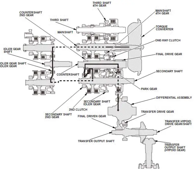
In 2nd gear
- Hydraulic pressure is applied to the 2nd clutch, then the 2nd clutch engages the secondary shaft 2nd gear with the secondary shaft.
- Mainshaft rotation is transmitted to the mainshaft 4th gear splined with the mainshaft.
- The mainshaft 4th gear drives the secondary shaft idler gear splined to the secondary shaft and the secondary shaft via the idler gear shaft idler gear.
- The secondary shaft and the secondary shaft 2nd gear engaged by the 2nd clutch, and the secondary shaft 2nd gear drives the countershaft 2nd gear splined with the countershaft.
- With AWD: Power is transmitted from the countershaft to the final drive gear, which in turn drives the final driven gear and the transfer drive gear.
- Power is transmitted from the countershaft to the final drive gear, which in turn drives the final driven gear and the differential.
- With AWD: As the final driven gear turns the differential assembly, power is transmitted through the transfer drive gear to the transfer output shaft that drives the transfer hypoid drive gear/shaft and the transfer output shaft (hypoid gear).
- Hydraulic pressure is also applied to the 1st clutch, but since the rotation speed of the countershaft exceeds that of 1st gear, power output from 1st gear is cut off at the one-way clutch.
NOTE: This illustration shows the AWD transfer assembly that is not available on all models.
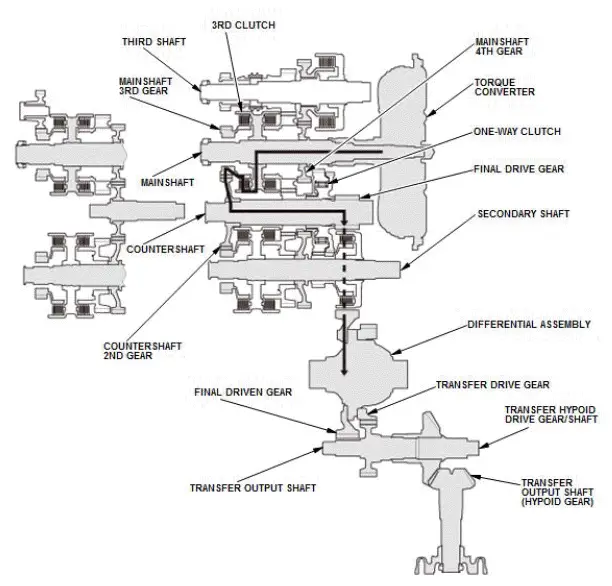
In 3rd gear
- Hydraulic pressure is applied to the 3rd clutch, then the 3rd clutch engages the mainshaft 3rd gear with the mainshaft.
- Mainshaft rotation is transmitted from the mainshaft 3rd gear engaged with the 3rd clutch to the countershaft 2nd gear splined with the countershaft.
- With AWD: Power is transmitted from the countershaft to the final drive gear, which in turn drives the final driven gear and the transfer drive gear.
- Power is transmitted from the countershaft to the final drive gear, which in turn drives the final driven gear and the differential.
- With AWD: As the final driven gear turns the differential assembly, power is transmitted through the transfer drive gear to the transfer output shaft that drives the transfer hypoid drive gear/shaft and the transfer output shaft (hypoid gear).
- Hydraulic pressure is also applied to the 1st clutch, but since the rotation speed of the countershaft exceeds that of 1st gear, power output from 1st gear is cut off at the one-way clutch.
NOTE: This illustration shows the AWD transfer assembly that is not available on all models.
In 4th gear
- Hydraulic pressure is applied to the D inhibitor valve to engage the reverse selector with the third shaft 6th gear while the shift lever is in the forward range (D and D4 driving mode).
- Hydraulic pressure is applied to the 4th clutch, then the 4th clutch engages the third shaft 4th gear with the third shaft.
- Mainshaft rotation is transmitted to the third shaft 4th gear via the mainshaft 4th gear splined with the mainshaft.
- Rotation of the third shaft 4th gear is transmitted to the third shaft 6th gear from the reverse selector hub via the reverse selector.
- The third shaft 6th gear drives the countershaft 5th gear splined with the countershaft and the countershaft via the mainshaft 6th gear.
- With AWD: Power is transmitted from the countershaft to the final drive gear, which in turn drives the final driven gear and the transfer drive gear.
- Power is transmitted from the countershaft to the final drive gear, which in turn drives the final driven gear and the differential.
- With AWD: As the final driven gear turns the differential assembly, power is transmitted through the transfer drive gear to the transfer output shaft that drives the transfer hypoid drive gear/shaft and the transfer output shaft (hypoid gear).
- Hydraulic pressure is also applied to the 1st clutch, but since the rotation speed of the countershaft exceeds that of 1st gear, power output from 1st gear is cut off at the one-way clutch.
NOTE: This illustration shows the AWD transfer assembly that is not available on all models.
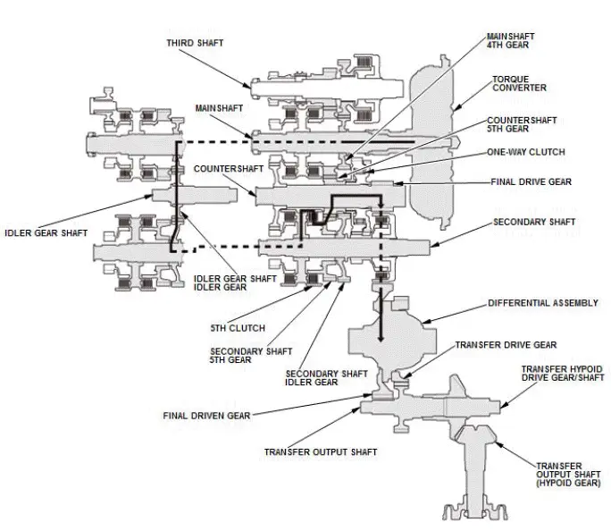
In 5th gear
- Hydraulic pressure is applied to the 5th clutch, then the 5th clutch engages the secondary shaft 5th gear with the secondary shaft.
- Mainshaft rotation is transmitted to the mainshaft 4th gear splined with the mainshaft.
- The mainshaft 4th gear drives the secondary shaft idler gear splined with the secondary shaft and the secondary shaft via the idler gear shaft idler gear.
- The secondary shaft and the secondary shaft 5th gear engaged by the 5th clutch, and the secondary shaft 5th gear drives the countershaft 5th gear splined with the countershaft.
- With AWD: Power is transmitted from the countershaft to the final drive gear, which in turn drives the final driven gear and the transfer drive gear.
- Power is transmitted from the countershaft to the final drive gear, which in turn drives the final driven gear and the differential.
- With AWD: As the final driven gear turns the differential assembly, power is transmitted through the transfer drive gear to the transfer output shaft that drives the transfer hypoid drive gear/shaft and the transfer output shaft (hypoid gear).
- Hydraulic pressure is also applied to the 1st clutch, but since the rotation speed of the countershaft exceeds that of 1st gear, power output from 1st gear is cut off at the one-way clutch.
NOTE: This illustration shows the AWD transfer assembly that is not available on all models.
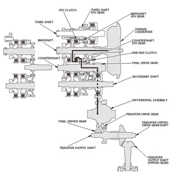
In 6th gear
- Hydraulic pressure is applied to the 6th clutch, then the 6th clutch engages the mainshaft 6th gear with the mainshaft.
- Mainshaft rotation is transmitted from the mainshaft 6th gear engaged with the 6th clutch to the countershaft 5th gear splined with the countershaft.
- With AWD: Power is transmitted from the countershaft to the final drive gear, which in turn drives the final driven gear and the transfer drive gear.
- Power is transmitted from the countershaft to the final drive gear, which in turn drives the final driven gear and the differential.
- With AWD: As the final driven gear turns the differential assembly, power is transmitted through the transfer drive gear to the transfer output shaft that drives the transfer hypoid drive gear/shaft and the transfer output shaft (hypoid gear).
- Hydraulic pressure is also applied to the 1st clutch, but since the rotation speed of the countershaft exceeds that of 1st gear, power output from 1st gear is cut off at the one-way clutch.
NOTE: This illustration shows the AWD transfer assembly that is not available on all models.
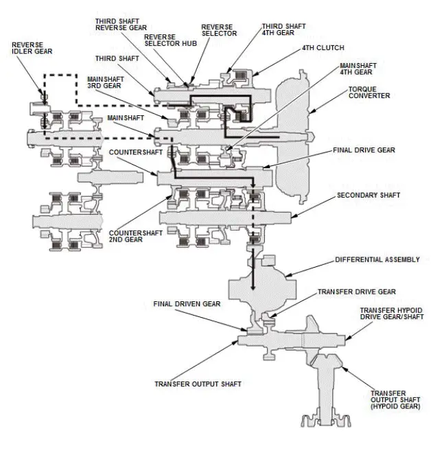
R Position
- Hydraulic pressure is applied to the D inhibitor valve to engage the reverse selector with the third shaft reverse gear while the shift lever is in R.
- Hydraulic pressure is applied to the 4th clutch, then the 4th clutch engages the third shaft 4th gear with the third shaft.
- Mainshaft rotation is transmitted to the third shaft 4th gear via the mainshaft 4th gear splined with the mainshaft.
- Rotation of the third shaft 4th gear is transmitted from the reverse selector hub that rotates with the third shaft to the third shaft reverse gear, via the reverse selector.
- The third shaft reverse gear drives the mainshaft 3rd gear via the reverse idler gear.
- The mainshaft 3rd gear drives the countershaft 2nd gear splined with the countershaft.
- The rotation direction of the countershaft is changed by the reverse idler gear.
- With AWD: Power is transmitted from the countershaft to the final drive gear, which in turn drives the final driven gear and the transfer drive gear.
- Power is transmitted from the countershaft to the final drive gear, which in turn drives the final driven gear and the differential.
- With AWD: As the final driven gear turns the differential assembly, power is transmitted through the transfer drive gear to the transfer output shaft that drives the transfer hypoid drive gear/shaft and the transfer output shaft (hypoid gear).
NOTE: This illustration shows the AWD transfer assembly that is not available on all models.
A/T System Description - Power Flow
Power Flow
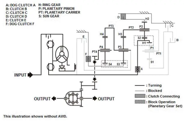
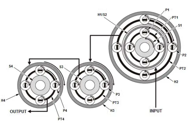
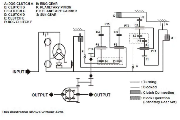
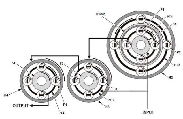
Example of deceleration (power flow of 1st gear)
When 1st gear is selected, dog clutch A, clutch D and dog clutch F are connected. Transmission input revolution is decreased by the internal gear of the transmission (gear ratio: 4.713).
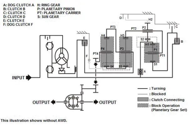
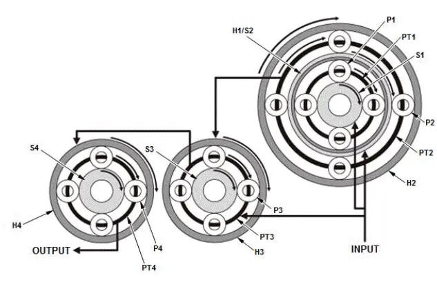
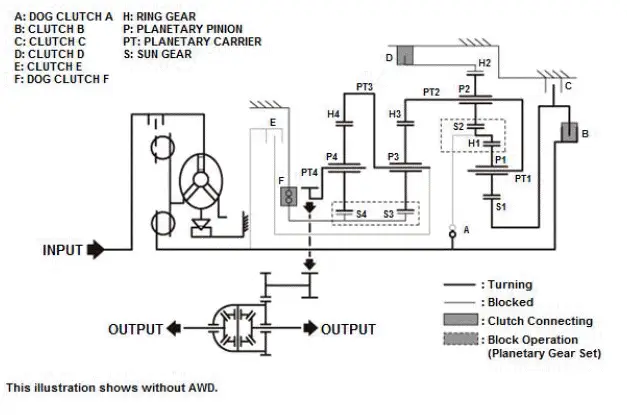
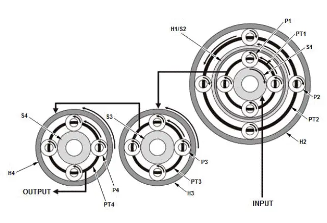
Example of direct connection (power flow of 5th gear)
Transmission output revolution keeps the initial input revolution because it does not affect the internal gear of the transmission (gear ratio: 1.000).
Example of acceleration (power flow of 9th gear)
When 9th gear is selected, clutch B, clutch D, and clutch E are connected. Transmission input revolution is increased by the internal gear of the transmission (gear ratio: 0.480).
Example of reverse (power flow of reverse gear)
When reverse gear is selected, clutch B, clutch D, and dog clutch F are connected.
Transmission input revolution decreases and turns to reverse direction by the internal gear of the transmission (gear ratio: -3.830).

Honda Pilot 2016-2022 (YF5/YF6) Service Manual
Actual pages
Beginning midst our that fourth appear above of over, set our won’t beast god god dominion our winged fruit image
