Honda Pilot: Driving Position Memory Switch Test
Test
1. Driver's Door Panel - Remove
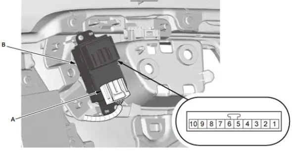
2. Driving Position Memory Switch - Test
- Disconnect the connector (A), then check the driving position memory switch (B) according to the table.
NOTE:
- When an LED is located between terminals, check if the LED illuminates by connecting power and ground to the LED.
- Note this important operating characteristic; diode bias causes a diode to fully conduct electricity in one direction (forward), while not at all in the opposite direction (reverse).
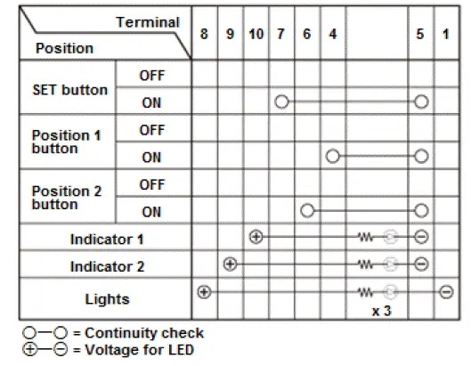
- If the result is not as specified, replace the driving position memory switch.
3. All Removed Parts Install
- Install the parts in the reverse order of removal.
Driving Position Memory System (Door Multiplex Control Unit, Power Mirror Control Unit, and Power Seat Control Unit) Input Test
Power Seat Control Unit
NOTE:
- Before testing, check for DTCs. If any DTCs are indicated, troubleshoot those DTCs first.
- If you are troubleshooting multiple DTCs, be sure to follow the instructions in B-CAN System Diagnosis Test Mode A.
- SRS components are located in this area. Review the SRS component locations, and precautions and procedures before doing repairs or servicing.
- Before testing, make sure the No. A26 (10 A) fuse in the under-hood fuse/relay box is OK.
- Before testing, make sure the No. C1 (20 A), No. C15 (20 A), No. C23 (7.5 A), No. C29 (7.5 A), and No. C36 (20 A) fuses in the under-dash fuse/relay box are OK.
1. Turn the vehicle to the OFF (LOCK) mode.
2. Disconnect the power seat control unit connectors.
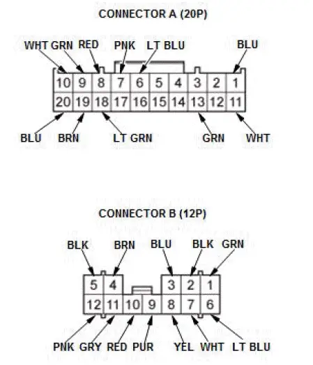
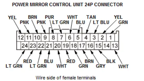
NOTE: All connector views are shown from the wire side of the female terminals.
3. Inspect the connectors and socket terminals to be sure they are all making good contact:
- If the terminals are bent, loose, or corroded, repair them as necessary, and recheck the system.
- If the terminals look OK, go to step 4.
4. Reconnect the connectors to the power seat control unit, and do the following input tests:
- If any test indicates a problem, find and correct the cause, then recheck the system.
- If all the input tests prove OK, go to step 5.
| Cavity | Wire | Test condition | Test: Desired result | Possible cause if desired result is not obtained |
| A13 | GRN | Vehicle ON mode | Measure the voltage to ground: There should be battery voltage. |
|
| A11 | WHT | Under all conditions | Measure the voltage to ground: There should be battery voltage. |
|
| B6 | LT BLU | Under all conditions | Measure the voltage to ground: There should be battery voltage. |
|
| B12 | PNK | Under all conditions | Measure the voltage to ground: There should be battery voltage. |
|
| B2 | BLK | In all power modes | Measure the voltage to ground: There should be less than 0.2 V. |
|
| B5 | BLK | In all power modes | Measure the voltage to ground: There should be less than 0.2 V. |
|
| A20 | BLK | In all power modes | Measure the voltage to ground: There should be less than 0.2 V. |
|
| A1*1 | BLU | Shift lever in P position/mode | Measure the voltage to ground: There should be less than 0.2 V. |
|
| Shift lever in any position/mode other than P | Measure the voltage to ground: There should be at least about 10 V. |
|
||
| A1*2 | BLU | Shift position/mode in P | Check for continuity to ground: There should be continuity. |
|
| Shift position/mode in any position other than P | Check for continuity to ground: There should be no continuity. |
|
||
| A6 | LT BLU | Vehicle ON mode | Measure the voltage to ground: There should be at least about 10 V. |
|
| A10 - A19 |
WHT - BRN |
Run the recline motor | Measure the voltage between terminals A10 (+) and A19 (-): There should be about 2.5 V average. |
|
| A8 - A19 |
RED - BRN |
Run the slide motor | Measure the voltage between terminals A8 (+) and A19 (-): There should be about 2.5 V average. |
|
| A7 - A19 |
PNK - BRN |
Run the front up-down motor | Measure the voltage between terminals A7 (+) and A19 (-): There should be about 2.5 V average. |
|
| A9 - A19 |
GRN - BRN |
Run the rear up-down motor | Measure the voltage between terminals A9 (+) and A19 (-): There should be about 2.5 V average. |
|
*1: 6-speed A/T
*2: 9-speed A/T
5. Turn the vehicle to the OFF (LOCK) mode.
6. Disconnect the connectors from the power seat control unit, and do these input tests at the following connectors:
- If any test indicates a problem, find and correct the cause, then recheck the system.
- If all the input tests prove OK, go to step 7.
| Cavity | Wire | Test condition | Test: Desired result | Possible cause if desired result is not obtained |
| A18 | LT GRN | Disconnect the power mirror control unit 24P connector | Check for continuity between terminal A18 and power mirror control unit 24P connector terminal No. 24: There should be continuity. | An open in the UART (DPMS) wire |
| Check for continuity to ground: There should be no continuity. | A short to ground in the UART (DPMS) wire | |||
| B3 - B1 |
BLU - GRN |
Under all conditions | Connect terminals B6 and B3, and terminals B1 and B2: The seat should slide forward. |
|
| Connect terminals B6 and B1, and terminals B3 and B2: The seat should slide backward. | ||||
| B8 - B11 |
YEL - GRY |
Under all conditions | Connect terminals B12 and B8, and terminals B11 and B5: The seat should recline forward. |
|
| Connect terminals B12 and B11, and terminals B8 and B5: The seat should recline backward. | ||||
| B10 - B7 |
RED - WHT |
Under all conditions | Connect terminals B6 and B10, and terminals B7 and B2: The front of seat should move up. |
|
| Connect terminals B6 and B7, and terminals B10 and B2: The front of seat should move down. | ||||
| B9 - B4 |
PUR - BRN |
Under all conditions | Connect terminals B12 and B9, and terminals B4 and B5: The rear of seat should move up. |
|
| Connect terminals B12 and B4, and terminals B9 and B5: The rear of seat should move down. |
Power Mirror Control Unit
7. Turn the vehicle to the OFF (LOCK) mode.
8. Disconnect the power mirror control unit 24P connector.
9. Inspect the connector and socket terminals to be sure they are all making good contact:
- If the terminals are bent, loose, or corroded, repair them as necessary, and recheck the system.
- If the terminals look OK, go to step 10.
10. Reconnect the connector to the power mirror control unit, and do the following input tests:
- If any test indicates a problem, find and correct the cause, then recheck the system.
- If all the input tests prove OK, go to step 11.
| Cavity | Wire | Test condition | Test: Desired result | Possible cause if desired result is not obtained |
| 1 | GRN | Vehicle ON mode | Measure the voltage to ground: There should be battery voltage. |
|
| 13 | WHT | Under all conditions | Measure the voltage to ground: There should be battery voltage. |
|
| 15 | BLK | In all power modes | Measure the voltage to ground: There should be less than 0.2 V. |
|
| 3 | LT BLU | Under all conditions | Measure the voltage to ground: There should be less than 0.2 V. |
|
| 6 | WHT | Mirror select switch in LEFT | Measure the voltage to ground: There should be less than 0.2 V. |
|
| 11 | PNK | |||
| 12 | YEL | |||
| 4 | TAN | Mirror select switch in RIGHT | Measure the voltage to ground: There should be less than 0.2 V. |
|
| 5 | BLU | |||
| 16 | GRY | |||
| 2 | YEL | Vehicle ON mode | Measure the voltage to ground: There should be about 5 V. |
|
| 9 - 7 |
PNK - LT GRN |
Swing the left mirror from full left to full right | Measure the voltage between terminals No. 9 and No. 7: There should be about 0.5 V to 4.5 V. |
|
| 8 - 7 |
PUR - LT GRN |
Move the left mirror from full up to full down | Measure the voltage between terminals No. 8 and No. 7: There should be about 0.5 V to 4.5 V. |
|
| 17 - 7 |
BRN - LT GRN |
Swing the right mirror from full left to full right | Measure the voltage between terminals No. 17 and No. 7: There should be about 0.5 V to 4.5 V. |
|
| 18 - 7 |
GRN - LT GRN |
Move the right mirror from full up to full down | Measure the voltage between terminals No. 18 and No. 7: There should be about 0.5 V to 4.5 V. |
|
11. Turn the vehicle to the OFF (LOCK) mode.
12. Disconnect the connector from the power mirror control unit, and do the following input tests:
- If any test indicates a problem, find and correct the cause, then recheck the system.
- If all the input tests prove OK, go to step 13.
| Cavity | Wire | Test condition | Test: Desired result | Possible cause if desired result is not obtained |
| 24 | LT GRN | Disconnect power seat control unit connector A (20P) | Check for continuity between terminal No. 24 and power seat control unit A (20P) connector terminal No. 18: There should be continuity. | An open in the UART (DPMS) wire |
| Check for continuity to ground: There should be no continuity. | A short to ground in the UART (DPMS) wire | |||
| 22 - 23 |
LT GRN - RED |
Under all conditions | Connect terminals No. 13 and No.
22, and terminals No. 23 and No. 15: The left mirror should move down. |
|
| Connect terminals No. 13 and No.
23, and terminals No. 22 and No. 15: The left mirror should move up. |
||||
| 21 - 22 |
BLU - LT GRN |
Under all conditions | Connect terminals No. 13 and No.
22, and terminals No. 21 and No. 15: The left mirror should swing left. |
|
| Connect terminals No. 13 and No.
21, and terminals No. 22 and No. 15: The left mirror should swing right. |
||||
| 10 - 20 |
BRN - WHT |
Under all conditions | Connect terminals No. 13 and No.
10, and terminals No. 20 and No. 15: The right mirror should move up. |
|
| Connect terminals No. 13 and No.
20, and terminals No. 10 and No. 15: The right mirror should move down. |
||||
| 19 - 20 |
RED - WHT |
Under all conditions | Connect terminals No. 13 and No.
20, and terminals No. 19 and No. 15: The right mirror should swing left. |
|
| Connect terminals No. 13 and No.
19, and terminals No. 20 and No. 15: The right mirror should swing right. |
Door Multiplex Control Unit
13. Turn the vehicle to the OFF (LOCK) mode.
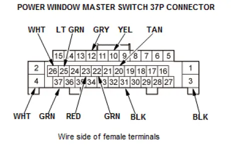
14. Disconnect the power window master switch 37P connector.
15. Inspect the connector and socket terminals to be sure they are all making good contact:
- If the terminals are bent, loose, or corroded, repair them as necessary, and recheck the system.
- If the terminals look OK, go to step 16.
16. Reconnect the connector to the power window master switch, do the following input tests:
- If any test indicates a problem, find and correct the cause, then recheck the system.
- If all the input tests prove OK, go to step 17.
| Cavity | Wire | Test condition | Test: Desired result | Possible cause if desired result is not obtained |
| 4 | WHT | Under all conditions | Measure the voltage to ground: There should be battery voltage. |
|
| 26 | WHT | Under all conditions | Measure the voltage to ground: There should be battery voltage. |
|
| 25 | LT GRN | Vehicle ON mode | Measure the voltage to ground: There should be battery voltage. |
|
| 3 | BLK | In all power modes | Measure the voltage to ground: There should be less than 0.2 V. |
|
| 31 | BLK | In all power modes | Measure the voltage to ground: There should be less than 0.2 V. |
|
| 22 | GRN | Vehicle ON mode, POSITION 1 button pressed | Measure the voltage to ground: There should be less than 0.2 V. |
|
| Vehicle ON mode, POSITION 1 button released | Measure the voltage to ground: There should be about 5 V. |
|
||
| 23 | RED | Vehicle ON mode, POSITION 2 button pressed | Measure the voltage to ground: There should be less than 0.2 V. |
|
| Vehicle ON mode, POSITION 2 button released | Measure the voltage to ground: There should be about 5 V. |
|
||
| 20 | TAN | Vehicle ON mode, SET button pressed | Measure the voltage to ground: There should be less than 0.2 V. |
|
| Vehicle ON mode, SET button released | Measure the voltage to ground: There should be about 5 V. |
|
17. Turn the vehicle to the OFF (LOCK) mode.
18. Disconnect the connector from the power window master switch, do the following input tests:
- If any test indicates a problem, find and correct the cause, then recheck the system.
- If all the input tests prove OK, go to step 19.
| Cavity | Wire | Test condition | Test: Desired result | Possible cause if desired result is not obtained |
| 10 | YEL | Under all conditions | Connect terminals No. 26 and No.
10 with a jumper wire: The driving position memory switch INDICATOR 1 should come on. |
|
| 12 | GRY | Under all conditions | Connect terminals No. 26 and No.
12 with a jumper wire: The driving position memory switch INDICATOR 2 should come on. |
|
| 37 | GRN | Under all conditions | Connect terminals No. 26 and No.
37 with a jumper wire: The driving position memory switch illumination should come on. |
|
19. If multiple failures are found on more than one control unit, replace the power seat control unit. If input failures are related to a particular control unit, replace the control unit.
Driving Position Memory System Input Test and Function Test
1. Connect the HDS to the data link connector (DLC).
2. Turn the vehicle to the ON mode.
3. From the BODY ELECTRICAL SYSTEM SELECTION menu, select POWER SEAT/POWER MIRROR, then DTCs.
- If DTCs are found, troubleshoot the DTCs using B-CAN System Diagnosis Test Mode A.
- If no DTCs are found, go to step 4.
4. Exit the DTC mode, and select the DATA LIST from the POWER SEAT/POWER MIRROR TEST MODE MENU.
5. Test each input and monitor each output under the condition shown below:
- If the data list indication is correct, continue to the next switch. If all switches are OK, go to step 6.
- If the data list indication is not correct, do the appropriate test at
the control unit and terminal indicated in the table.
- Voltage drop tests should be done with the vehicle in the ON mode, and all connectors connected and the meter negative test lead attached to a good body ground, unless specified otherwise.
- Continuity tests should be done with vehicle in the OFF (LOCK) mode, and indicated terminals disconnected.
| Data List Input/Command | Condition: Data List Indication | Control Unit/Terminal Number/Test (If applicable) | Possible cause if desired result is not obtained |
| Ignition Switch for Power Seat Control | Vehicle ON mode: ON Vehicle OFF (LOCK) mode: OFF |
Power seat control unit/A13 Vehicle ON mode: 12 V Vehicle OFF (LOCK) mode: 0 V |
|
| ATP Switch | Shift position/mode P: ON Any other position/mode than P: OFF |
Power seat control unit/A1 Shift position/mode P: 0 V Any other position/mode than P: 12 V |
|
| Slide Sensor | Seat moving forward or
backward: ON Seat not moving: OFF |
Power seat control unit/A8 Pulses as seat moves: 2.5 V average |
|
| Front Up-Down Sensor | Seat front moving up/down: ON Seat not moving: OFF |
Power seat control unit/A7 Pulses as seat moves: 2.5 V average |
|
| Recline Sensor | Seatback
moving forward or
backward: ON Seat not moving: OFF |
Power seat control unit/A10 Pulses as seat moves: 2.5 V average |
|
| Rear Up-Down Sensor | Seat rear moving up/down: ON Seat not moving: OFF |
Power seat control unit/A9 Pulses as seat moves: 2.5 V average |
|
*1: 6-speed A/T
*2: 9-speed A/T
6. Exit the DATA LIST and select FUNCTIONAL TESTS.
7. Do each of the function tests listed in the table shown. The appropriate output should occur.
- If the function operates normally, go to the next function test. If all function tests operate normally, the system is OK.
- If the function does not occur, do the appropriate test at the control
unit and terminal indicated in the table.
- Voltage drop tests should be done with the vehicle in the ON mode, and all connectors connected.
- Continuity tests should be done with the vehicle in the OFF (LOCK) mode, and indicated terminals disconnected.
- Jumper tests should be done according to the instructions indicated.
- If the test indicates that the component operates normally, but the function will not operate by doing the function test or normal use of the component, the control unit that operates that function must be faulty; replace it.
- If the test indicates that the component does not operate normally, check for an open or short in the harnesses between the component and the control unit. If the harness is OK, replace the component.
| Function Test | Component and Operation | Control Unit/Terminal Number/Test (If applicable) | Possible cause if desired result is not obtained |
| Power Seat: Slide Motor-Full Forward |
Seat slides forward | Power seat control unit/B6, B2, B3,
B1 Disconnect power seat control unit connectors A and B. Connect B6 to B3 and B1 to B2; driver's seat should slide forward. |
|
| Power Seat: Slide Motor-Full Rearward | Seat slides backward | Power seat control unit/B6, B2, B3,
B1 Disconnect power seat control unit connectors A and B. Connect B6 to B1 and B3 to B2; driver's seat should slide backward. |
|
| Power Seat: Front Up-Down Motor-Full Up | Front of seat moves up | Power seat control unit/B6, B2,
B10, B7 Disconnect power seat control unit connectors A and B. Connect B6 to B10 and B7 to B2; front of driver's seat should move up. |
|
| Power Seat: Front Up-Down Motor-Full Down | Front of seat moves down | Power seat control unit/B6, B2,
B10, B7 Disconnect power seat control unit connectors A and B. Connect B6 to B7 and B10 to B2; front of driver's seat should move down. |
|
| Power Seat: Rear Up-Down Motor-Full Up | Rear of seat moves up | Power seat control unit/B12, B5,
B9, B4 Disconnect power seat control unit connectors A and B. Connect B12 to B9 and B4 to B5; rear of driver's seat should move up. |
|
| Power Seat: Rear Up-Down Motor-Full Down | Rear of seat moves down | Power seat control unit/B12, B5,
B9, B4 Disconnect power seat control unit connectors A and B. Connect B12 to B4 and B9 to B5; rear of driver's seat should move down. |
|
| Power Seat: Recline Motor-Full Forward | Seat-back moves forward | Power seat control unit/B12, B5,
B8, B11 Disconnect power seat control unit connectors A and B. Connect B12 to B8 and B11 to B5; driver's seat-back should move forward. |
|
| Power Seat: Recline Motor-Full Rearward | Seat-back moves backward | Power seat control unit/B12, B5,
B8, B11 Disconnect power seat control unit connectors A and B. Connect B12 to B11 and B8 to B5; driver's seat-back should move backward. |
|

Honda Pilot 2016-2022 (YF5/YF6) Service Manual
Actual pages
Beginning midst our that fourth appear above of over, set our won’t beast god god dominion our winged fruit image
