Honda Pilot: EPS System Description - Motion Adaptive-EPS Control
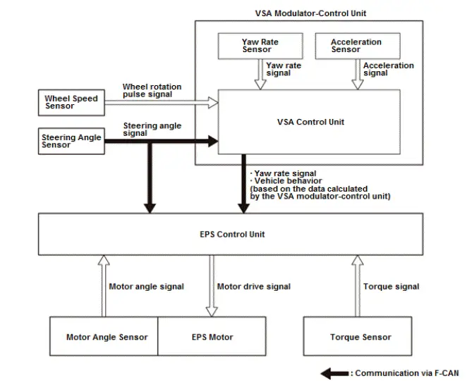
Motion adaptive-EPS control performs the steering torque correction control coordinated with VSA system for stabilizing the vehicle when the steering is unstable. The EPS system determines the state of the vehicle based on the data calculated by the VSA modulator-control unit, and the data from the yaw rate sensor and the acceleration sensor. When the system determines that the vehicle behavior is abnormal, the EPS control unit calculates the correction current based on the vehicle behavior and corrects the steering torque.
The motion adaptive-EPS control is stopped in the event of failure in the VSA system.
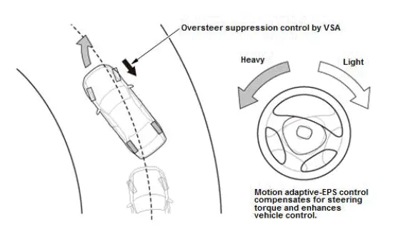
Mitigates Oversteer Control
When oversteer occurs, it compensates for steering torque to steer in the countersteer direction, and enhances vehicle control.
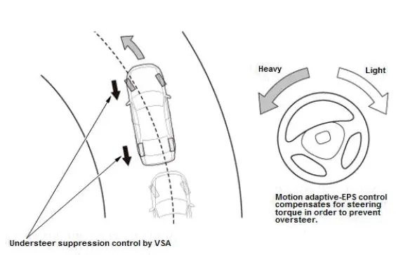
Mitigates Understeer Control
When understeer occurs, it compensates for steering torque to control oversteer, then holds the tire grip to enhance vehicle control.
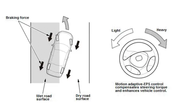
Stabilizes Braking on Road Surfaces With Different Friction Coefficients Control
When the vehicle behavior is abnormal while braking on an uneven road surface, it compensates for steering torque to enhance vehicle control.
EPS System Description - Overview
System Outline
This vehicle is equipped with electrical power steering (EPS)
The driver's steering force is assisted by an electric motor at the steering column. Compared to a hydraulic assist power steering system, EPS is more efficient because it does not need an engine driven oil pump to generate hydraulic pressure.
The EPS control unit monitors and controls the EPS motor's assisting force to match driving conditions.
- Low vehicle speeds: High power assist (for easy handling)
- High speed driving: Low power assist (for stable driving)
- Low speed to high speed driving: Change smoothly from high assist to low assistv
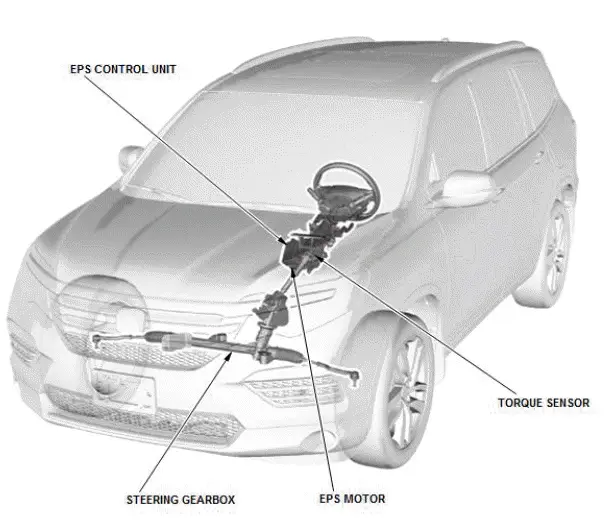
The EPS control unit, the EPS motor, the torque sensor are combined into the steering column.
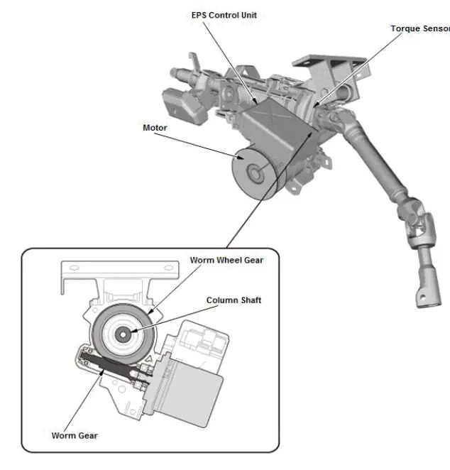
EPS System Description - Steering Column
The steering force from the steering wheel is sent to the column shaft. The torque sensor measures the difference between the force applied to the column shaft and the resistance to turning the wheels due to road friction, and converts it to a voltage signal which is sent to the EPS control unit. Based on this signal, the EPS control unit controls the current to the EPS motor. The EPS motor rotates the worm gear which is engaged to the worm wheel gear which is part of the column shaft. This becomes the assist force in the steering system.
EPS System Description - System Diagram
The system diagram of the EPS system is shown below.
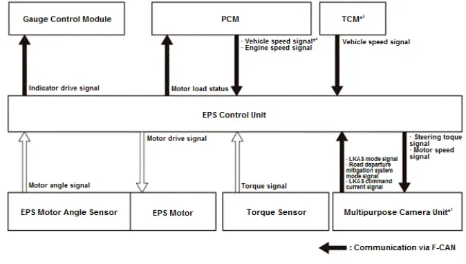
*1: With LKAS
*2: 6-Speed A/T
*3: 9-Speed A/T

Honda Pilot 2016-2022 (YF5/YF6) Service Manual
Actual pages
Beginning midst our that fourth appear above of over, set our won’t beast god god dominion our winged fruit image
