Honda Pilot: PGM-FI System Description - Injection Control
Fuel injection controls include fuel injection amount control, fuel cut control, and fuel pump control. Adaptive PGM-FI (programmed- fuel injection) technology enables accurate fuel controls, which contributes to increasing engine power and decreasing fuel consumption.
Fuel Injection
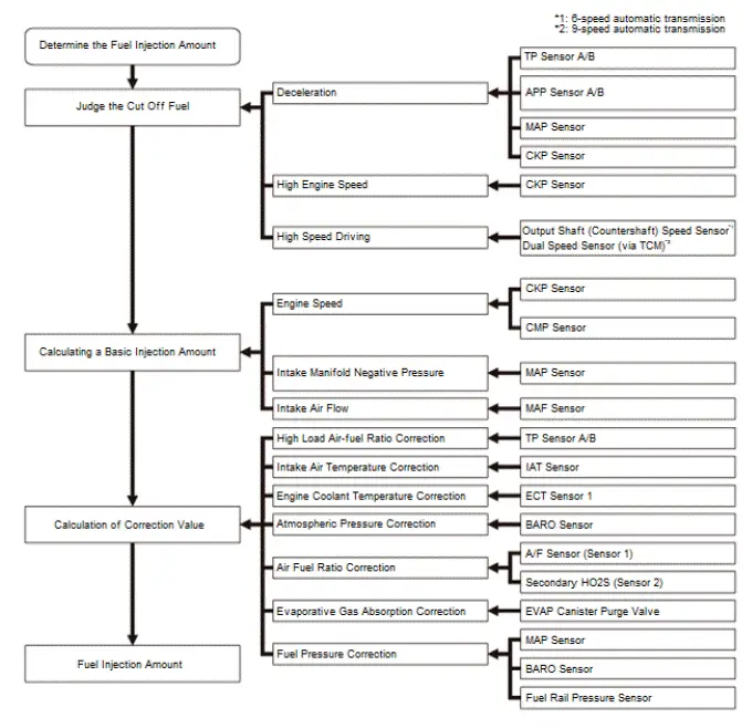
The fuel injection is determined by adding correction values to a basic injection. The powertrain control module (PCM) controls the amount of fuel injection by the length of time the injector is energized.
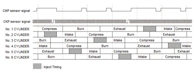
Fuel Injection Timing
The fuel injection timing is determined by the PCM, which calculates the injection time for each cylinder based on the signals sent from the crankshaft position (CKP) sensor and the camshaft position (CMP) sensor. The PCM then controls the time to energize the injector.
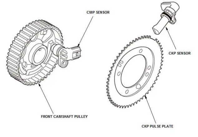
CKP Sensor
The CKP sensor is attached to the engine block. Each of the 58 teeth on the CKP pulse plate passes over the CKP sensor, which generates a pulse signal that is delivered to the the PCM.
CMP Sensor
The camshaft position (CMP) sensor is attached to the back cover of the front bank. Every time one of the five protrusions of the pulse plate attached to the camshaft passes over CMP sensor, which generates a pulse signal that is delivered to the PCM.
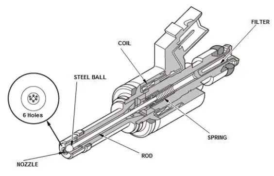
Fuel Injector
The fuel injectors are installed on the cylinder head and use multiple nozzles to inject high pressure fuel into the combustion chamber.
Six injection ports promotes a finer fuel spray and improved fuel consumption by reducing fuel adherence to the top surface of the piston, reduction of hydrocarbons (HC) discharge, and higher engine performance.
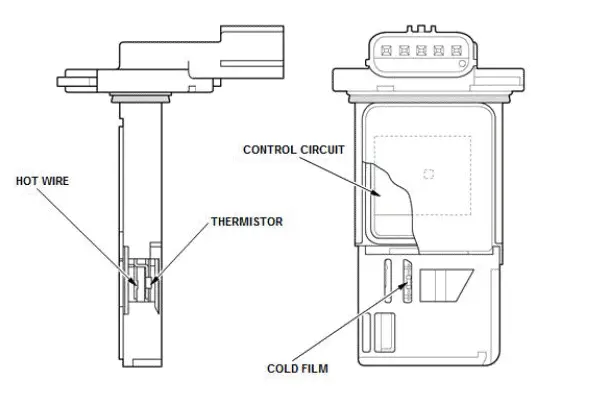
MAF Sensor/IAT Sensor
The MAF sensor/IAT sensor is located in the intake air passage and contains a hot wire sensor, a cold wire sensor and a thermistor.
The resistance of the hot wire sensor, the cold wire sensor, and the thermistor changes due to intake air temperature and air flow. The control circuit in the MAF sensor controls the current to keep the hot wire at a set temperature. The current is converted to voltage in the control circuit, then outputted to the PCM.
PGM-FI System Description - OBD
Overview
The on-board diagnostic detects failures in the emission control system. If any of the failure items in the table is detected by it, the failure is notified to the driver via the MIL in the gauge control module.
For details of the failure items, refer to the DTC troubleshooting index.
Two Drive Cycle Detection Method
When a malfunction occurs in the signal from a sensor or from another control unit in the first drive cycle, the powertrain control module (PCM) stores a pending DTC. The MIL does not come on at this time. If the failure continues in the second drive cycle, the PCM stores a confirmed DTC and turns on the MIL.
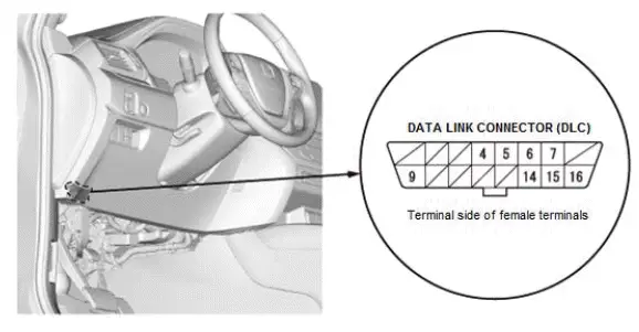
HDS (Honda Diagnostic System)
The data link connector (DLC) is under the driver's side of the dashboard. The DLC is used to connect the HDS or other scan tool to the vehicle for system diagnosis and troubleshooting.
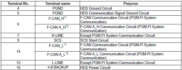
*1: 6-speed automatic transmission
*2: 9-speed automatic transmission

Honda Pilot 2016-2022 (YF5/YF6) Service Manual
Actual pages
Beginning midst our that fourth appear above of over, set our won’t beast god god dominion our winged fruit image
