Honda Pilot: Variable Cylinder Management Rocker Arm Test
Test
1. Ignition Coil and Spark Plug - Remove
2. Cylinder Head Cover - Remove
3. VTEC Rocker Arm - Test
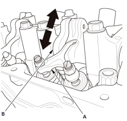
Front Bank
- Rotate the crankshaft pulley clockwise. Make sure that the
intake primary rocker arm (A) should move independently
of the intake secondary rocker arm (B):
- If the intake primary and secondary rocker arms do not move independently, remove the intake primary and secondary rocker arms as an assembly, and check that the pistons in the rocker arms move smoothly. If any intake rocker arm needs replacing, replace the primary and secondary rocker arms as an assembly, then retest.
- If the intake primary and secondary rocker arms move independently, go to step 2.
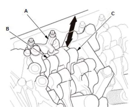
Rear Bank
- Rotate the crankshaft pulley clockwise. Make sure that the
intake primary rocker arm (A) and the intake secondary L
rocker arm (B) should move together, on the other hand,
intake primary rocker arm and the intake secondary H
rocker arm (C) should move independently:
- If the intake primary and secondary L rocker arms do not move together, remove the intake primary, secondary L and H rocker arms as an assembly, and check that the pistons in the rocker arms move smoothly. If any intake rocker arm needs replacing, replace the intake primary, secondary rocker arms L and H as an assembly, then retest.
- If the intake primary rocker arm and the intake secondary L rocker arms move together, go to step 3.
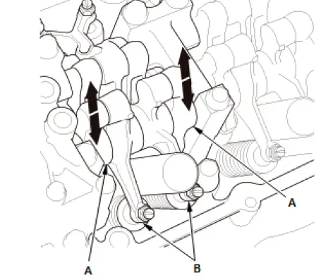
- Rotate the crankshaft pulley clockwise. Make sure that the
exhaust primary rocker arms (A) and the exhaust
secondary rocker arms (B) are mechanically connected by
the pistons and that the exhaust primary rocker arm and
the exhaust secondary rocker arms should move together:
- If the exhaust primary and secondary rocker arms do not move together, remove the exhaust primary and secondary rocker arms as an assembly, and check that the pistons in the rocker arms move smoothly. If any exhaust rocker arm needs replacing, replace the exhaust primary and secondary rocker arms as an assembly, then retest.
- If the exhaust primary and secondary rocker arms move together, go to the next procedure.
4. Air Pressure - Check
- Check that the air pressure on the shop air compressor gauge indicates over 690 kPa (7.04 kgf/cm2, 100.1 psi).
5. Valve Clearance - Inspect
6. VTEC/VCM Change Over - Test
Front (VTEC)
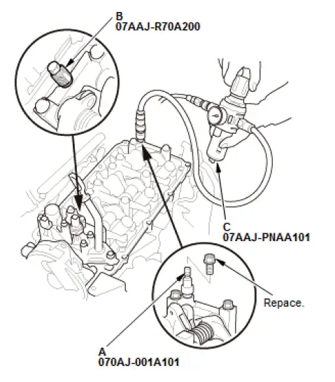
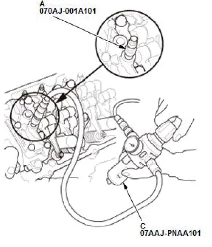
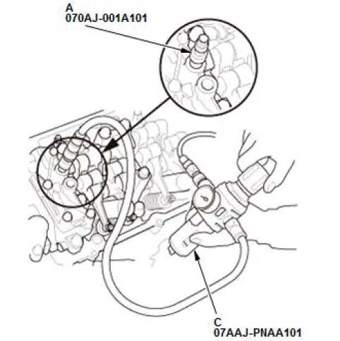
- Remove the sealing bolt, then install the VCM air adapter (A) to the inspection hole and install VTEC air stop tool B, then connect the air pressure regulator (C) as shown.
- Loosen the valve on the air pressure regulator, and apply the specified air pressure.
Specified Air Pressure
441-490 kPa (4.50-5.00 kgf/cm2, 64.0-71.1 psi)
Rear (VTEC)
Rear (VCM)
Front (VTEC)
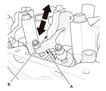
- With the specified air pressure applied, rotate the
crankshaft pulley clockwise. Make sure that the intake
primary rocker arm (A) and the intake secondary rocker
arm (B) are mechanically connected by the pistons and that the intake
primary and secondary rocker arms should move
together:
- If the intake primary and secondary rocker arms move independently, remove the intake primary and secondary rocker arms as an assembly, and check that the pistons in the rocker arms move smoothly. If any intake rocker arm needs replacing, replace the primary and secondary rocker arms as an assembly, then retest.
- If the intake primary and secondary rocker arms move together, go to step 4.
Rear (VTEC)
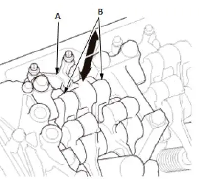
- With the specified air pressure applied, rotate the
crankshaft pulley clockwise. Make sure that the intake
primary rocker arm (A) and the intake secondary L and H
rocker arms (B) are mechanically connected by the pistons
and that the intake primary and secondary L and H rocker
arms should move together:
- If the intake primary and secondary L and H rocker arms move independently, remove the intake primary, secondary L and H rocker arms as an assembly, and check that the pistons in the rocker arms move smoothly. If any intake rocker arm needs replacing, replace the primary, secondary L and H rocker arms as an assembly, then retest.
- If the intake primary and secondary L and H rocker arms move together, go to step 5.
Rear (VCM)
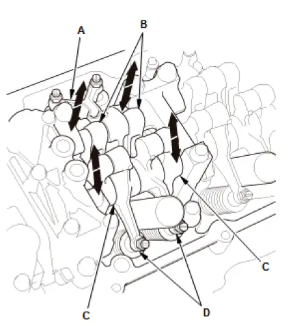
- With the specified air pressure applied, rotate the
crankshaft pulley clockwise. Make sure that the intake
primary rocker arm (A) should move independently of the
intake secondary L and H rocker arms (B). The exhaust
primary rocker arms (C) should move independently of the
exhaust secondary rocker arms (D):
- If the intake primary, secondary L and H rocker arms do not move independently, remove the intake primary, secondary L and H as an assembly, and check that the pistons in the rocker arms move smoothly. If any intake rocker arm needs replacing, replace the primary, secondary L and H as an assembly, then retest.
- If the exhaust primary and secondary rocker arms do not move independently, remove the exhaust primary and secondary rocker arms as an assembly, and check that the pistons in the rocker arms move smoothly. If any exhaust rocker arm needs replacing, replace the exhaust primary and secondary rocker arms as an assembly, then retest.
- If the intake primary and secondary L and H rocker arms, and exhaust primary and secondary rocker arms move independently, go to next procedure.
7. All Special Tools - Remove
8. Sealing Bolt - Install
- Torque the new sealing bolts to 22 N-m (2.2 kgf-m, 16 lbf-ft).
9. All Removed Parts - Install
- Install the parts in the reverse order of removal.
Ventilated Seat Control Unit Input Test
NOTE:
- Before testing, check for DTCs. If any DTCs are indicated, troubleshoot those DTCs first.
- If you are troubleshooting multiple DTCs, be sure to follow the instructions in B-CAN System Diagnosis Test Mode A.
- Before testing, check the No. C17 (20 A) fuse in the under-dash fuse/relay box is OK.
- Before testing, check the No. D1 (7.5 A) fuse in the auxiliary under-dash fuse/relay box is OK.
1. Disconnect the ventilated seat control unit 14P connector.
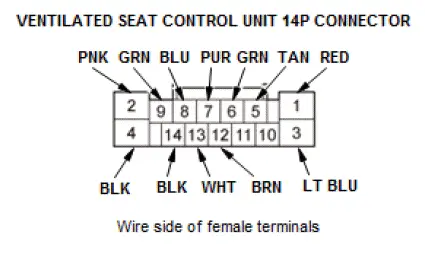
2. Inspect the connector and socket terminals to be sure they are all making good contact:
- If the terminals are bent, loose or corroded, repair them as necessary, and recheck the system.
- If the terminals are OK, go to step 3.
3. With the connector still disconnected, do the following input tests:
- If any test indicates a problem, find and correct the cause, then recheck the system.
- If all the input tests prove OK, go to step 4.
| Cavity | Wire | Test condition | Test: Desired result | Possible cause if desired result is not obtained |
| 7 | PUR | Under all conditions | Check for continuity between terminals No. 7 and No. 13: There should be continuity. |
|
| 13 | WHT | |||
| 6 | GRN | Under all conditions | Check for continuity between terminals No. 6 and No. 12: There should be continuity. |
|
| 12 | BRN |
4. Reconnect the connector, and do the following input tests:
- If any test indicates a problem, find and correct the cause, then recheck the system.
- If all the input tests prove OK, replace the ventilated seat control unit.
| Cavity | Wire | Test condition | Test: Desired result | Possible cause if desired result is not obtained |
| 2 | PNK | Vehicle ON mode | Measure the voltage to ground: There should be battery voltage. |
|
| 9 | GRN | Vehicle ON mode | Measure the voltage to ground: There should be battery voltage. |
|
| 4 | BLK | In all power modes | Measure the voltage to ground: There should be less than 0.2 V. |
|
| 14 | BLK | In all power modes | Measure the voltage to ground: There should be less than 0.2 V. |
|
| 5 | TAN | Vehicle ON mode, passenger's seat cushion blower motor and passenger's seat-back blower motor ON mode | Measure the voltage to ground: There should be battery voltage. |
|
| 8 | BLU | Vehicle ON mode, driver's seat cushion blower motor and driver's seat-back blower motor ON mode | Measure the voltage to ground: There should be battery voltage. |
|
| 1 | RED | Vehicle ON mode, driver's seat heater ON mode | Measure the voltage to ground: There should be battery voltage. |
|
| 3 | LT BLU | Vehicle ON mode, front passenger's seat heater ON mode | Measure the voltage to ground: There should be battery voltage. |
|
Special Tool Required
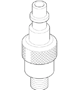
- VCM Air Adapter 070AJ-001A101
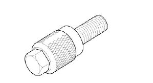
- VTEC Air Stop Tool B 07AAJ-R70A200
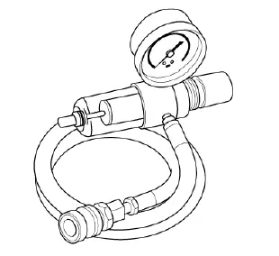
- Air Pressure Regulator 07AAJ-PNAA101

Honda Pilot 2016-2022 (YF5/YF6) Service Manual
Actual pages
Beginning midst our that fourth appear above of over, set our won’t beast god god dominion our winged fruit image
