Honda Pilot: A/T Road Test
Test
1. Engine - Warm Up
- Start the engine. Hold the engine speed at 3,000 rpm without load (in P or N) until the radiator fan comes on, then let it idle.
2. HDS DLC - Connect
3. Vehicle - Road-Test
- Park the vehicle on level ground.
- Apply the parking brake, and block all four wheels.
- Start the engine.
- Shift to D while pressing the brake pedal. Press the accelerator pedal, and release it suddenly. The engine should not stall.
- Repeat step 4 in all shift lever positions.
- Prepare the HDS and the MVCI to take a SNAPSHOT (refer to the HDS user's guide for more details if needed).
- Set the Trigger Type to Parameter.
- Adjust the Parameter setting to APP Sensor A (V) above 1.1 V.
- Set the Recording Time to 60 seconds.
- Set the Trigger Point to (Negative)-30 seconds.
- Find a suitable level road.
- When you are ready to do the test, press OK on the HDS.
- Accelerate quickly until APP Sensor A (V) reads 1.3 V.
Maintain a steady throttle until the transmission shifts to 6th gear, then slow the vehicle and come to a stop.
- Save the snapshot if the entire event was recorded or increase the recording time setting as necessary, and repeat step 9.
- Adjust the Parameter setting to 2.2 V.
- Test-drive the vehicle again. Accelerate quickly until APP Sensor A (V) reads 2.3 V. Maintain a steady throttle until the transmission shifts to 6th gear (or a reasonable speed), then slow the vehicle and come to a stop.
- Save the snapshot if the entire event was recorded or increase the recording time setting as necessary, and repeat step 12.
- Accelerate quickly until the accelerator pedal is to the floor.
Maintain a steady pedal until the transmission shifts to 5th gear, then slow to a stop, and save the snapshot.
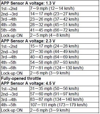
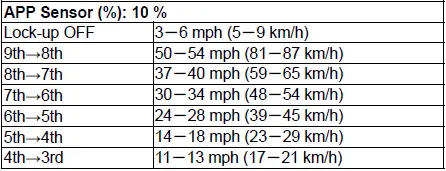
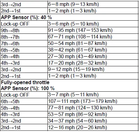
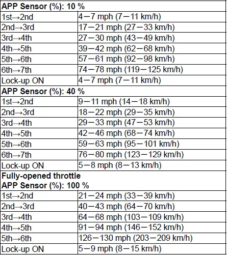
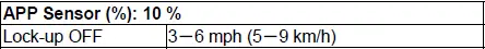
- Review each snapshot individually, and compare the Shift Control, APP Sensor A (V), and the Vehicle Speed to the following table.
Upshift: D Position
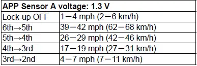
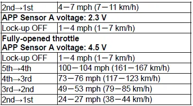
Downshift: D Position
- Shift to R, accelerate from a stop at full throttle momentarily, and check for abnormal noise and clutch slippage.
- Park the vehicle on an upward slope (about 16 degrees),
apply the parking brake, then shift into P. Release the
parking brake; the vehicle should not move.
NOTE: Always use the parking brake to hold the vehicle when stopped on an incline in gear. Depending on the grade of the incline, the vehicle could roll if the parking brake is released.
A/T Road Test
Test
1. HDS DLC - Connect
2. Engine - Warm Up
- Start the engine, and warm it up to normal operating temperature (the radiator fan comes on twice).
- Turn the engine off.
3. Vehicle - Road-Test
- Park the vehicle on level ground.
- Apply the parking brake, and block all four wheels.
- Start the engine.
- Shift the transmission to D position/mode while pressing the brake pedal. Press the accelerator pedal, and release it suddenly. The engine should not stall.
- Repeat step 4 in S and R position/mode.
- Prepare the HDS and the MVCI to take a SNAPSHOT (refer to the HDS user's guide for more details if needed).
- Set the Trigger Type to Parameter.
- Adjust the Parameter setting of the APP Sensor (%) to 9 %.
- Set the Recording Time to 60 seconds.
- Set the Trigger Point to (Negative)-30 seconds.
- Find a suitable level road.
- When you are ready to do the test, press OK on the HDS.
- Accelerate quickly until the APP Sensor (%) reads 10 %. Maintain a steady throttle until the vehicle reaches a reasonable speed, then slow the vehicle and come to a stop.
- Save the snapshot if the entire event was recorded or increase the recording time setting as necessary, and repeat step 9.
- Adjust the Parameter setting to 39 %.
- Test-drive the vehicle again. Accelerate quickly until the APP Sensor (%) reads 40 %. Maintain a steady throttle until the vehicle reaches a reasonable speed, then slow the vehicle and come to a stop.
- Save the snapshot if the entire event was recorded or increase the recording time setting as necessary, and repeat step 12.
- Accelerate quickly until the accelerator pedal is to the floor. Maintain a steady pedal until the vehicle reaches a reasonable speed, then slow to a stop, and save the snapshot.
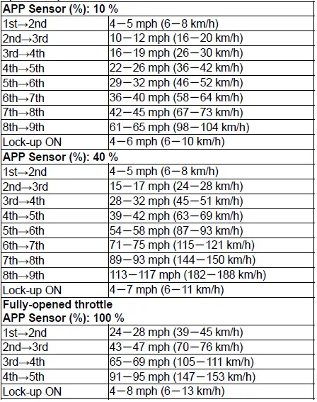
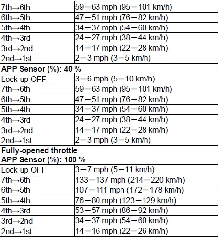
- Review each snapshot individually, and compare the Gear Shifting, the APP Sensor (%), and the Vehicle Speed to the following table.
Upshift: D position/mode
Downshift: D position/mode
Upshift: S position/mode
Downshift: S Position
- Drive the vehicle in 9th gear, then decelerate and downshift to 2nd gear. The vehicle should immediately begin to slow down from the engine braking, then slow to a stop.
- Shift the transmission to R position/mode, accelerate from a stop at full throttle momentarily, and check for abnormal noise and clutch slippage.
- Park the vehicle on an upward slope (about 16 degrees), apply the
parking brake, then shift the transmission to P
position/mode. Release the parking brake; the vehicle should not move.
NOTE: Always use the parking brake to hold the vehicle when stopped on an incline in gear. Depending on the grade of the incline, the vehicle could roll if the parking brake is released.
AC Inverter Unit Input Test
NOTE:
- Before testing, make sure the No. A27 (30 A) fuse in the under-hood fuse/relay box is OK.
- Before testing, make sure the No. C23 (7.5 A) fuse in the under-dash fuse/relay box is OK.
- Turn the vehicle to the OFF (LOCK) mode.
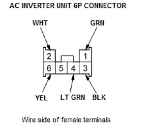
- Disconnect the AC inverter unit 6P connector.
- Inspect the connector and socket terminals to be sure they are all
making good contact:
- If the terminals are bent, loose, or corroded, repair them as necessary, and recheck the system.
- If the terminals are OK, go to step 4.
- With the connector still disconnected, do the following input tests:
- If any test indicates a problem, find and correct the cause, then recheck the system.
- If all the input tests prove OK, go to step 5.
| Cavity | Wire | Test condition | Test: Desired result | Possible cause if desired result is not obtained |
| 6 | YEL | Under all conditions | Check for continuity between terminal No. 6 and power outlet 3P connector terminal No. 1: There should be continuity. | An open or high resistance in the ground wire |
| 2 | WHT | Under all conditions | Check for continuity between terminal No. 2 and power outlet 3P connector terminal No. 3: There should be continuity. | An open or high resistance in the ground wire |
- Reconnect the connector, and do the following input tests:
- If any test indicates a problem, find and correct the cause, then recheck the system.
- If all the input tests prove OK, replace the AC inverter unit.
| Cavity | Wire | Test condition | Test: Desired result | Possible cause if desired result is not obtained |
| 4 | LT GRN | Vehicle ON mode | Measure the voltage to ground: There should be battery voltage. |
|
| 1 | GRN | Under all conditions | Measure the voltage to ground: There should be battery voltage. |
|
| 3 | BLK | Under all conditions | Measure the voltage to ground: There should be less than 0.2 V. |
|

Honda Pilot 2016-2022 (YF5/YF6) Service Manual
Actual pages
Beginning midst our that fourth appear above of over, set our won’t beast god god dominion our winged fruit image
