Honda Pilot: A/T System Description - Electronic Control System
Electronic Control
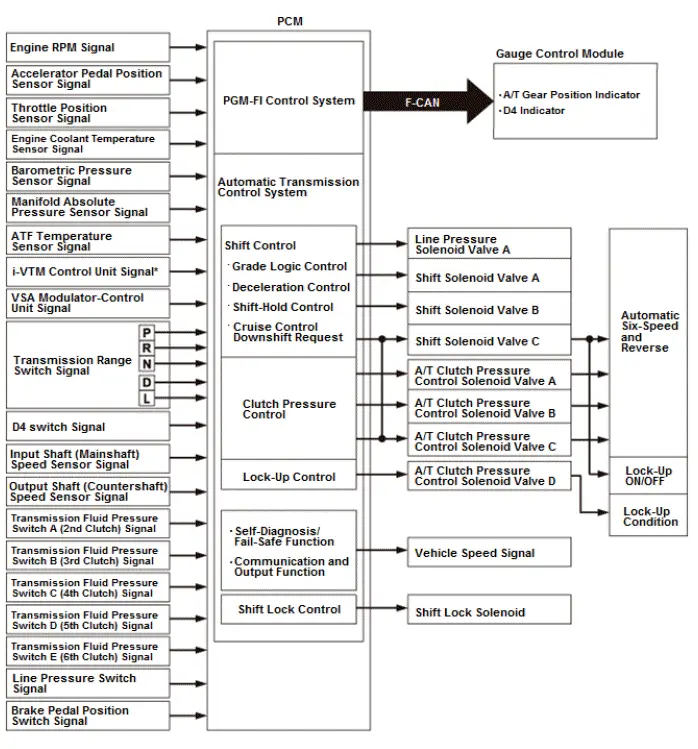
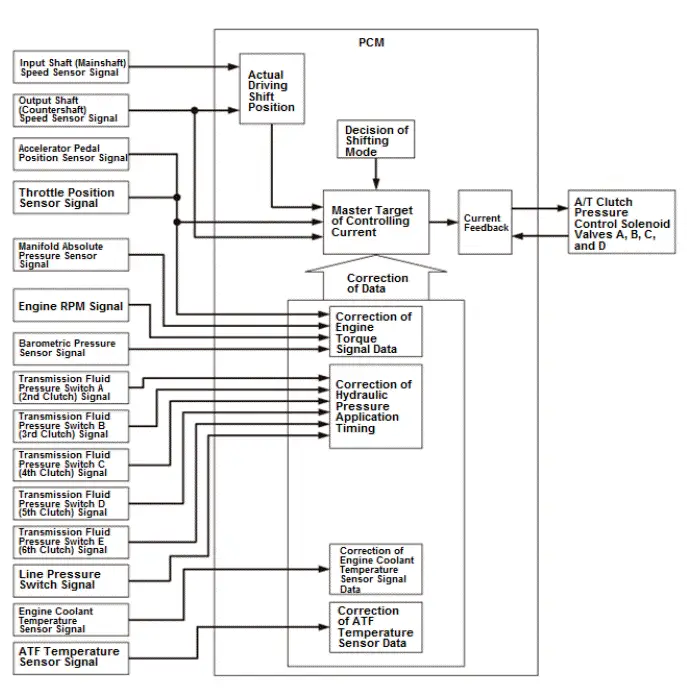
The PCM receives input signals from the sensors, switches, and other control units, processes data, and outputs signals for the engine control system and the A/T control system. The A/T control system includes shift control, clutch pressure control, lock-up control, and A/T system hydraulic control. The PCM switches the shift solenoid valves and the A/T clutch pressure control solenoid valves ON and OFF in a specific sequence to control gear selection and the torque converter clutch lock-up. It also controls the appropriate operating hydraulic pressure to the automatic transmission.
*1: With AWD
Shift Control
The PCM instantly determines which gear should be selected by various inputs from sensors and switches, and it actuates the solenoid valves to control gear selection.
A/T clutch pressure control solenoid valve:
A/T clutch pressure control solenoid valves A, B, C, and D apply hydraulic pressure to each clutch via the hydraulic valve body circuit.
A/T clutch pressure control solenoid valve D supplies hydraulic pressure to the torque converter clutch. A/T clutch pressure control solenoid valves A, B, C, and D are normally closed (ON-OPEN/OFF-CLOSE); the normally closed solenoid valve port opens to allow ATF to pass through when the PCM turns it ON, and the port closes, blocking fluid flow when turned OFF. These solenoid valves are controlled by current and are duty controlled depending on the vehicle speed and the throttle position.
Line pressure solenoid valve:
Line pressure solenoid valve A controls the hydraulic pressure in the hydraulic control system valve bodies of the automatic transmission. Line pressure solenoid valve A is normally closed (ON-OPEN/OFF-CLOSE); the normally closed solenoid valve port opens to allow ATF to pass through when the PCM turns it ON, and the port closes, blocking fluid flow when turned OFF.
Shift Control - Grade Logic Control
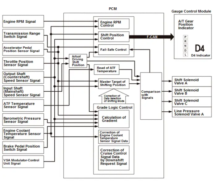
The grade logic control system is used to control shifting in D, and D4 driving mode. The PCM compares actual driving conditions with programmed driving conditions, based on the input signal from the throttle position sensor, the engine coolant temperature sensor, the barometric pressure sensor, the brake pedal position switch, and the transmission range switch to switch shifting control from the normal control to the ascending or descending control when the PCM determines that the vehicle is ascending a slope or being driven down a slope.
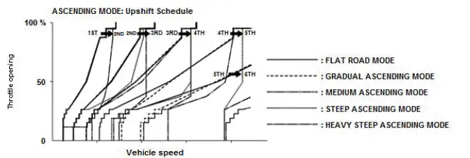
Grade Logic Control: Ascending Control
When the PCM determines that the vehicle is climbing a hill in D the system extends the engagement area of 2nd gear, 3rd gear, 4th gear, and 5th gear to prevent the transmission from frequently shifting between 2nd and 3rd gears, between 3rd and 4th gears, between 4th and 5th gears, and between 5th and 6th gears, so the vehicle can run smoothly and have more power when needed.
NOTE: Shift commands stored in the PCM between 2nd and 3rd gears, between 3rd and 4th gears, between 4th and 5th gears, and between 5th and 6th gears, enable the PCM to automatically select the most suitable gear based on the steepness of the grade.
Grade Logic Control: Descending Control
When the PCM determines that the vehicle is going down a hill in D the upshift speed from 5th to 6th gear, from 4th to 5th gear, from 3rd to 4th gear, and from 2nd to 3rd (when the throttle is closed) becomes higher than the set speed for flat road driving to extend the 5th gear, 4th gear, 3rd gear, and 2nd gear driving conditions and modes. This, in combination with engine braking from the deceleration lock-up, achieves smooth driving when the vehicle is descending. There are descending modes stored in the PCM with different 5th gear, 4th gear, 3rd gear, and 2nd gear driving conditions and modes based on the steepness of the grade. When the vehicle is in 6th, 5th, or 4th gear, and the vehicle is decelerating while applying the brakes on a steep hill, the transmission downshifts to a lower gear. When you accelerate, the transmission then returns to a higher gear.
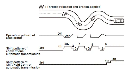
Deceleration Control
When the vehicle goes around a corner and needs to decelerate first and then accelerate, the PCM goes into the deceleration control mode to reduce the number of times the transmission shifts. When the vehicle is decelerating from speeds above 27 mph (43 km/h), the PCM anticipates upcoming acceleration, and shifts the transmission from 4th to 3rd earlier than normal.
Shift-Hold Control
Shift-hold control maintains transmission gear position during cornering to avoid frequently shifting. When the vehicle is cornering, the PCM extends the engagement of 2nd, 3rd, 4th, and 5th to prevent the transmission from frequently shifting between 3rd, 4th, 5th, and 6th gears. When the PCM determines that the vehicle is cornering by the accelerator pedal position, the vehicle speed, and the lateral G-force estimate from the rpm difference between each wheel, it delays the upshift from 3rd to 4th, 4th to 5th, and 5th to 6th gears, which improves the engine output and the engine braking. The transmission resumes the normal upshift pattern after the PCM determines that normal driving has resumed.
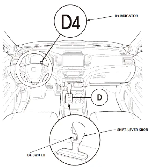
Shift Control - D Position D4 Driving Mode Control
This automatic transmission is equipped with a D4 driving mode in D. D has two modes; general driving mode (shifts gears automatically 1st through 6th), and the D4 driving mode (shifts gears automatically 1st through 4th). The transmission switches mode when you press the D4 switch on the shift lever knob in D.
In D4 driving mode, the D4 indicator next to the D indicator in the gauge assembly comes on. The D4 driving mode is cancelled by pushing the D4 switch, and the D4 indicator goes off. Also, the D4 driving mode is cancelled when turning the vehicle to the OFF (LOCK) mode. When the shift lever is moved out of D in the D4 driving mode, the D4 indicator goes off, but the transmission returns to the D4 driving mode when the shift lever returned to D, and the D4 indicator comes on.
Clutch Pressure Control
The PCM actuates A/T clutch pressure control solenoid valves A, B, C, and D to control the clutch pressure. When shifting between gears or during lock-up, the clutch pressure is regulated by A/T clutch pressure control solenoid valves A, B, C, and D engages and disengages the clutch smoothly. The PCM receives input signals from the various sensors and switches, then the processes data, and outputs current to A/T clutch pressure control solenoid valves A, B, C, and D.
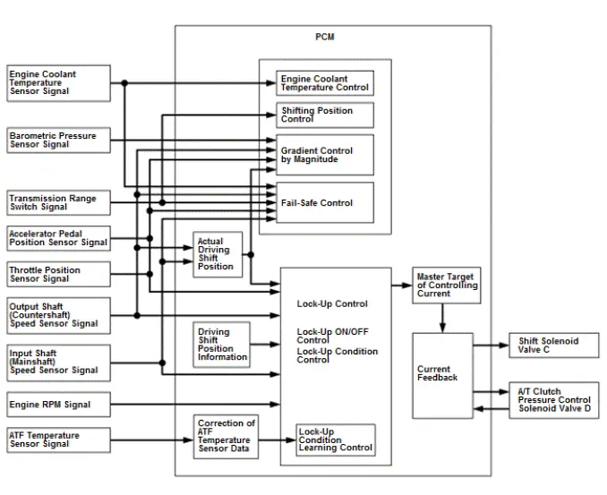
Lock-Up Control
Shift solenoid valve C and A/T clutch pressure control solenoid valve D control the hydraulic pressure to switch the lock-up shift valve and lock-up ON and OFF. When the PCM actuates shift solenoid valve C and A/T clutch pressure control solenoid valve D ON, lock- up starts. A/T clutch pressure control solenoid valve D applies and regulates hydraulic pressure to the lock-up control valve to control the amount of lock-up.
The lock-up mechanism operates:
- D - accelerating in 1st, 2nd, 3rd, 4th, 5th, and 6th gears
- D - decelerating in 2nd, 3rd, 4th, 5th, and 6th gears
- D4 driving mode - accelerating in 1st, 2nd, 3rd, and 4th gears
- D4 driving mode - decelerating in 2nd, 3rd, and 4th gears
- L - accelerating in 1st and 2nd gears
- L - decelerating in 2nd gear
A/T System Description - Electronic Control System
Electronic Control System
Electronic Control
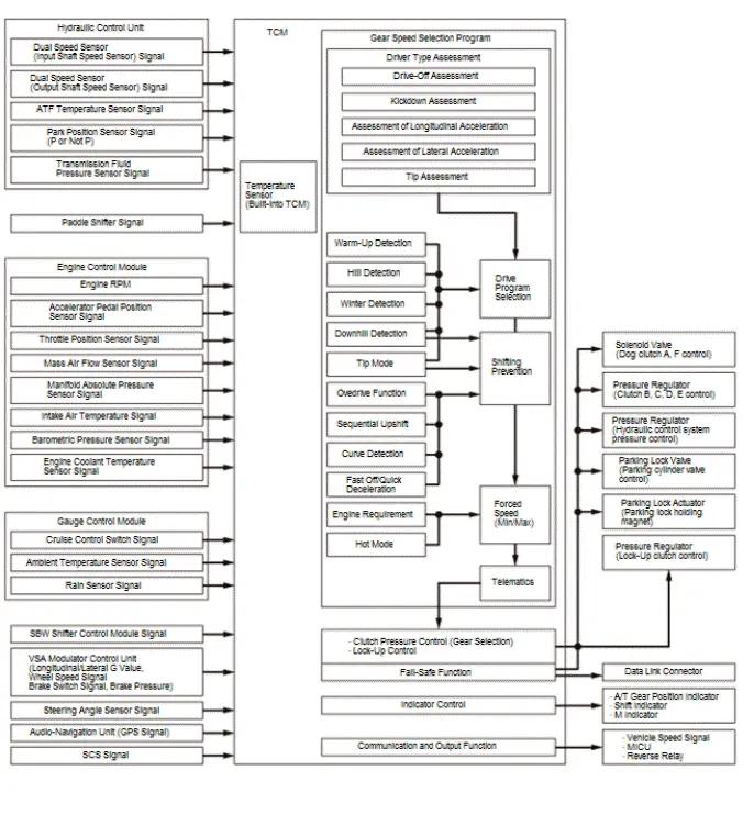
The TCM receives input signals from the sensors, switches, and other control units, processes data, and outputs signals for the A/T control system. The A/T control system includes shift control, clutch pressure control, lock-up control, and A/T system hydraulic control. The TCM switches the solenoid valves and the pressure regulators ON and OFF in a specific sequence to control gear selection and the torque converter clutch lock-up. It also controls the appropriate operating hydraulic pressure of the automatic transmission.
Shift Control - Grade Logic Control
The grade logic control system is used to control shifting.
The TCM compares actual driving conditions with programmed driving conditions, based on the input signal from various sensors, switches, and other control units, to switch shifting control from the normal control to the ascending or descending control when the TCM determines that the vehicle is ascending a slope or being driven down a slope. When the vehicle is in a rapid slowdown condition, the TCM may select the skip shift. It can skip over the gear in the shift down of descending order.
Shift Control - S Mode
With the S position/mode, optimum driving force and engine brake performance are achieved by proactive downshifting and low gear selection. Also in this mode, the sequential shift mode can be selected by pressing the paddle shifter.
Adaptive Shift Strategy (ASIS)
The computer programs (software) required for controlling the automatic transmission can be divided into several groups. One group of these programs is the adaptive shift strategy (ASIS). ASIS combines functions which detect and assess outside influences on the selection of the correct drive program at any given time.
These outside influencing variables are the followings; driver type detection, warm-up detection, hill detection, downhill detection, tip mode, winter detection, gear ratios with overdrive character, sequential upshift, cornering, fast off/quick deceleration.
Driver type assessment
The driver type assessment is a transmission function which assesses the driving style with regard to sportiness and, if a sporty driving style has been detected, adjusts the shift program according to the following criteria.
- Drive-off assessment
- The drive-off assessment evaluates the intensity of each starting process in relation to the maximum engine torque. If a driver starts the vehicle at a higher load or even at full throttle, a sporty shift program is assigned to this driver immediately.
- Kickdown assessment
- Kickdown is a downshift position in which the maximum engine output is required. If the driver permanently remains in kickdown, the sportiness counter is cyclically (gradually) increased.
- Assessment of longitudinal acceleration
- The longitudinal acceleration describes how quickly the vehicle changes (accelerates or decelerates) from the current speed to another one. This variable takes into account positive (heavy accelerating) and negative (heavy braking) acceleration and the sportiness counter is increased correspondingly. With a constant driving style, the sportiness counter is decreased again.
- Assessment of lateral acceleration
- Lateral acceleration is the force pushing the vehicle outwards when cornering. The amount of this force depends on vehicle speed and steering angle. The vehicle has to exceed a defined lateral acceleration threshold before the assessment function receives the information that the vehicle is currently undergoing a fast cornering maneuver and the sportiness counter is cyclically (gradually) increased independent of the driving style.
- Tip assessment
- If the driver manually intervenes in gear selection, this is detected by ASIS. It will not only take into account manual shifting but, optionally, also how often these occur during a certain period of time.
Driving situation/environment detection
Depending on external circumstances, certain driving situations or environmental conditions are detected and taken into account during gear selection.
- Warm-up detection
- The warm-up program is temporarily selected if the engine temperature is below a specified temperature threshold. It is to promptly support catalyst warm-up and reduce pollutant emissions when the engine is cold. During this temporary driving program, shift points optimized for warm-up are used. The warm-up program is terminated prematurely when driving uphill or downhill.
- Hill detection
- The hill detection is based on deviations from the equilibrium between the driving force (engine torque) and the driving resistance at the drive wheels. The following factors influencing the external driving resistance are taken into account; rolling resistance of tires, vehicle weight (and inertia), aerodynamics (aerodynamic drag), climbing resistance. When driving uphill or downhill, the driver is therefore not required to intervene in order to achieve an earlier downshift or later upshift. When driving up a slope in high gear, the downshift will automatically be performed earlier than on level ground due to the load increase. In addition, the drive program is automatically adjusted to the current load condition or even to trailer operation merely based on the elevated driving resistance.
- Winter detection
- This function enables higher gears to be selected when driving on road surfaces with low friction coefficients such as; in ice and snow, in rain, on loose and soft ground. This helps facilitate starting the vehicle and avoid downshifting which could result in hazardous driving situations.
- Tip mode
- If a tip function (manual shifting) is provided for control elements, the input signals for upshift (paddle shifter+) and downshift (paddle shifter-) can be used to intervene in automatic gear selection. How the tip commands are implemented under which driving conditions can be determined flexibly depending on customer requirements. Those tip requests which cannot be executed as they might harm the engine or transmission are generally ignored. For example, starting in a higher gear or downshift at high speeds which could lead to overspending.
- Downhill detection
- As with hill detection, downhill detection is also based on driving resistance calculations. However, it also takes into account the manner in which the brake pedal is actuated. When driving downhill, the driver is therefore not required to manually intervene in gear selection with a possible downshift in order to achieve an increased engine braking effect. The electronic system uses the following input parameters to detect whether and when a corresponding downshift to the next lower gear to support the brake force or an upshift lock is required; load position of the accelerator pedal, vehicle speed, actuation of the brake pedal, downhill inclination/driving resistance.
- Overdrive function
- Due to the high number of gears in modern automatic transmissions and the demanding requirements relating to an economic driving style, one or several gears are designed with an override character. These high-ratio gears enable consumption- optimized driving at low speeds. At high speeds, these gears lack the torque reserve which is why an upshift lock is applied upon load downshift.
- Sequential upshift
- When leaving a function such as curve detection, fast off, etc. which caused an upshift lock to be applied, any pending upshift operations are executed one after the other (= sequentially) in a time-delayed manner without overriding any gear ratios.
- Curve detection
- Curve detection is a function which causes an upshift lock to be applied in fast cornering to ensure safety and/or maintain cornering stability. If the current lateral acceleration or steering angle exceeds a defined threshold, a curve is detected. The upshift lock is only released after having driven for a defined distance following the curve.
- Fast off/quick deceleration
- This transmission function is based on the assessment of the position and movement (high negative pedal gradient) of the accelerator pedal and detects the driver's intentions. If the driver suddenly releases the accelerator pedal, an upshift lock is applied. A fast load reduction is very often triggered by either a hazardous situation or sporty cornering; in both cases, upshifting (as would be intended by the shift program for low accelerator pedal values) would be unnecessary. The upshift lock upon fast off detection is released as soon as the driver accelerates again.
- Engine Requirement
- Further possible variables influencing gear selection are engine requirements causing gear changes to be executed such that the engine and transmission remain within a predetermined speed range (upper and lower forced speed threshold).
- Telematics
- Gear selection may be based on environment data (on topography) supplied by the telematic system (GPS).
Manual Shift Mode
The paddle shifters enable the transmission to be up-shifted or down-shifted manually when the paddle shifters are operated by the driver. The paddle shifters are installed on the back of the steering wheel and the driver can shift gears by pressing the paddle shifters without taking either hand off the steering wheel. The transmission is provided with a D-paddle shift mode and with a sequential shift mode. Both modes are entered by pressing the paddle shifter while driving.
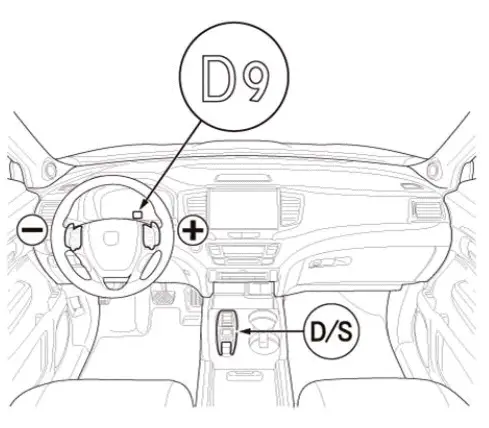
Manual Shift Mode - D-Paddle Shift Mode
When the paddle shifter is pressed while in the D position/mode (selected by the D/S switch of SBW shifter), the D-paddle shift mode comes into operation.
In the D-paddle shift mode, the transmission can shift into a lower gear or a higher gear by pressing the paddle shifter. The D-paddle shift mode is canceled when the paddle shifter + (upshift switch) is held for several seconds or when the PCM detects a steady cruise.
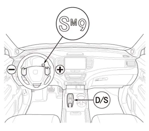
Manual Shift Mode - Sequential Shift Mode
When the paddle shifter is pressed while in the S position/mode (selected by the D/S switch of SBW shifter), the sequential shift mode comes into operation. The shift indicator displays the number of the selected gear and the M indicator comes on.
In the sequential shift mode, the driver can shift up and down manually by using the paddle shifters much like a manual transmission. The sequential shift mode is canceled when the paddle shifter + (upshift switch) is held for several seconds or when the S position/mode is canceled.
Shift By Wire
General Description
The SBW system (Shift By Wire system) is a system that performs the shift operations of the driver electrically instead of using control cables. This system is composed of the SBW shifter control module (built-into the SBW shifter assembly), the PCM, the TCM, etc. A push switch type SBW shifter permitting change to any position by one touch is used offering reduced shift operation force and excellent operability.
Electronic Control
When the driver operates the SBW shifter assembly, the SBW shifter control module transmits a shift position signal to the TCM. The TCM energizes the pressure regulators and the solenoid valves in the hydraulic control unit, and then performs the shifting operation. When selecting the P position/mode, shifting to the P position/mode is done by activating the solenoid valve and the parking lock actuator. Also, shifting to the P position/mode is done automatically for safety in the following cases; in case of door opened while driving in any other than P position/mode (vehicle speed less than 1 mph (2 km/h) ), in case of vehicle turned to the OFF mode while driving in any other than P position/mode (vehicle speed less than 1 mph (2 km/h) ). The TCM informs the SBW shifter control module whether the transmission is now in the P position/mode or not.
Neutral Position Holding Mode
This system is configured in such a way that the P position/mode is entered automatically when the vehicle is turned to the OFF mode. For this reason, a neutral position holding mode is provided when it is desired to stay in the N position/mode even when the vehicle is in the OFF mode. The neutral position holding mode keeps the transmission in the N position for approximately 15 minutes after the vehicle is turned to the OFF mode.
Function For Prevention Of Erroneous Operation
A function for prevention of erroneous operation is provided to ensure that the operating safety is maintained at all times, even in case of a handling error in regard to the SBW shifter assembly.
| Operations where the function for prevention of erroneous operation is activated | Shift position after the function for prevention of erroneous operation was activated |
| When the brake pedal is not pressed at the time of shifting from the P position/mode | P |
| When the accelerator pedal is pressed at the time of shifting from the P position/mode | P |
| When the brake pedal is not pressed at the time of shifting from the N position/mode | N |
| When the accelerator pedal is pressed at the time of shifting from the N position/mode | N |
| When the vehicle speed is above 1 mph (2 km/h) at the time of parking switch operation | N |
| When the vehicle speed is above 5 mph (8 km/h) at the time of shifting from the D position/mode to the R position/mode | N |
| When the vehicle speed is above 8 mph (12 km/h) at the time of shifting from the R position/mode to the D position/mode | N |

Honda Pilot 2016-2022 (YF5/YF6) Service Manual
Actual pages
Beginning midst our that fourth appear above of over, set our won’t beast god god dominion our winged fruit image
