Honda Pilot: A/T System Description - General Operation
The automatic transmission is a transverse-mounted five-shaft design with an electronically controlled hydraulic circuit that provides six forward speeds and one in reverse. Engine output is transmitted through the torque converter, a combination of shafts which hold gears and clutches and a differential that transmits power to the driving wheels. AWD equipped model also has a transfer assembly which transmits power to the AWD differential.
Shaft, Gears, and Clutches
The clutches and gears are installed on the input shaft (mainshaft), the secondary shaft, the third shaft, and the idler gear shaft. These gears are in constant mesh with those on the output shaft (countershaft). When specific gears are engaged by the clutches, power is transmitted through the mainshaft, to the secondary shaft, the third shaft, the idler gear shaft, and/or the countershaft, then to the final driven gear of the differential to provide drive.
Shift Control Mechanism
To perform hydraulic control, shift control, and lock-up control of the automatic transmission, the PCM controls shift solenoid valves A, B, and C, line pressure solenoid valve A, and automatic transmission (A/T) clutch pressure control solenoid valves A, B, C, and D.
The PCM switches each shift solenoid valve ON and OFF. This changes the positions of the shift valves in the valve bodies which open and close ports to send hydraulic pressure to the appropriate clutch. A/T clutch pressure control solenoid valves A, B, C, and D control the clutch pressure regulated by each of them, which allows smooth shifts and lock-up of the torque converter.
Electronic Control
Shifting and lock-up are achieved by a system of solenoid valves driven by the PCM, which controls ATF flow through various valves in the valve bodies to select the appropriate gears for all driving conditions.
Hydraulic Control
The valve bodies consist of the main valve body, the regulator valve body, the secondary valve body, the stator shaft support, and the manual valve body. They are installed to the torque converter housing. Fluid regulated by the regulator valve passes through the manual valve to the various control valves. All clutches receive fluid from the shaft internal hydraulic circuit. Also, the hydraulic control body is adapted to the secondary valve body, which includes the main shift hydraulic circuit, the solenoid valve, the hydraulic switch, etc. to shorten the fluid passage and optimize the hydraulic pressure.
Torque Converter
The torque converter is connected to the drive plate. It consists of an impeller (pump), turbine, stator, and torque converter clutch piston, which uses ATF to transmit engine power to the input shaft (mainshaft). Around the outside of the torque converter housing, the starter ring gear is installed, which is used to start the engine.
Lock-Up Mechanism
The lock-up causes the input shaft (mainshaft) to rotate at the same speed as the engine crankshaft by engaging the torque converter cover with the turbine by the torque converter clutch. Together with the hydraulic control, the PCM optimizes the timing and degree of lock-up. The lock-up mechanism operates in D (during accelerating: 1st, 2nd, 3rd, 4th, 5th, and 6th gears/during decelerating: 2nd, 3rd, 4th, 5th, and 6th gears), D4 driving mode (during accelerating: 1st, 2nd, 3rd, and 4th gears/during decelerating: 2nd, 3rd, and 4th gears), and in L (during accelerating: 1st and 2nd gears/during decelerating: 2nd gear). The torque converter clutch is in the torque converter. The multi-plate torque converter clutch increases the torque capacity and increases the lock-up clutch surface area, improving fuel economy and durability.
Gear Selection
The shift lever has five positions; P: PARK, R: REVERSE, N: NEUTRAL, D: DRIVE 1st through 6th gear ranges with automatic shift mode, D4 driving mode 1st through 4th gear ranges with automatic shift mode, and L: LOW 1st and 2nd gear ranges.
| Position | Description |
| P: PARK | Front wheels locked; the park pawl engaged with the park gear on the countershaft. All clutches are released. |
| R: REVERSE | Reverse; the reverse selector engaged with the third shaft 4th gear and the 4th clutch engaged. |
| N: NEUTRAL | All clutches are released. |
| D: DRIVE (1st through 6th gear) | General driving; starts off in 1st gear, shifts to 2nd, 3rd, 4th, 5th, then 6th gear, depending on the vehicle speed and the throttle position. Downshifts through 5th, 4th, 3rd, 2nd, and 1st gear on deceleration to stop. The lock-up mechanism operates in 1st through 6th gears while accelerating, and in 2nd through 6th gears while decelerating. |
| D: DRIVE with D4 driving mode (1st through 4th) | Used for rapid acceleration at highway speeds and general driving, up-hill and down-hill driving; starts off in 1st, shifts automatically to 2nd, 3rd then 4th, depending on vehicle speed and accelerator pedal position. Downshifts through 3rd, 2nd and 1st on deceleration to stop. The lock-up mechanism operates in 1st through 4th gears while accelerating, and in 2nd, 3rd through 4th gears while decelerating. |
| L: LOW | Used for engine braking; starts off in 1st gear, shifts to 2nd gear, depending on the vehicle speed and the throttle position. Downshifts to 1st gear on deceleration to stop. The lock-up mechanism operates in 1st and 2nd gears while acceleration, and in 2nd gear while decelerating. |
Starting the engine is possible only in P and N because of a neutral-safety switch built into the transmission range switch.
Automatic Transmission (A/T) Gear Position Indicator
The A/T gear position indicator in the gauge control module shows which shift lever position that has been selected.
Shift Indicator
When you operate the paddle shift switch, the shift indicator in the gauge control module displays the gear selected. The shift indicator also displays the gear selected in the D-paddle shift mode and the sequential sportshift mode.
Transfer Assembly (With AWD)
The transfer assembly consists of the transfer hypoid drive gear/shaft assembly, the transfer output shaft (hypoid gear), and the companion flange. The transfer assembly is on the rear side of the transmission, beside the differential. The transfer drive gear on the differential drives the transfer output shaft in the transmission. The transfer output shaft in the transmission is connected to the transfer hypoid drive gear/shaft assembly by splines. Power is transmitted from the transfer drive gear on the differential to the rear differential via the transfer assembly and the propeller shaft.
A/T System Description - General Operation
General Operation
The automatic transmission has four planetary gear sets and six clutches and allows the gears to change (forward of 9 steps, reverse of 1 step). To change the gears, the solenoid valves and the pressure regulators in the hydraulic control unit switch hydraulic passages and are controlled by the transmission control module (TCM).
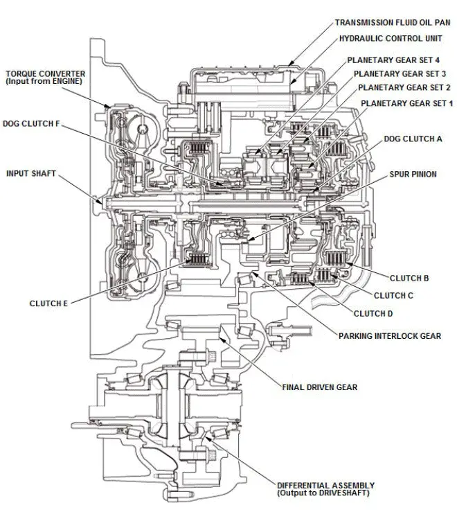
Torque Converter
The torque converter is connected to the drive plate. It consists of a pump wheel, turbine wheel, stator and a torsional damper, which uses ATF to transmit engine power to the input shaft.
Lock-Up Mechanism
Together with the hydraulic control, the TCM optimizes the timing and degree of lock-up by controlling the solenoid.
Gear Selection
The shift position/mode has five positions; P: PARK, R: REVERSE, N: NEUTRAL, D: DRIVE (1st through 9th gear ranges with automatic shift mode and D-paddle shift mode), and S: SPORT DRIVE (1st through 8th gear ranges with automatic shift mode and 1st through 9th gear ranges with sequential shift mode).
Shift Indicator and M Indicator
When you operate the paddle shifter, the shift indicator in the gauge control module displays the selected gear. The shift indicator also displays the selected gear in the D-paddle shift mode and the sequential shift mode.
A/T System Description - General Operation
General Operation
The automatic transmission has four planetary gear sets and six clutches and it is possible to change the gears (forward of 9 steps, reverse of 1 step) by them. To change the gears, the solenoid valves and the pressure regulators in the hydraulic control unit switch hydraulic passages and are controlled by the transmission control module (TCM).
Torque Converter
The torque converter is connected to the drive plate. It consists of a pump wheel, turbine wheel, stator and a torsional damper, which uses ATF to transmit engine power to the input shaft.
Lock-Up Mechanism
Together with the hydraulic control, the TCM optimizes the timing and degree of lock-up by controlling the solenoid.
Gear Selection
The shift position/mode has five positions; P: PARK, R: REVERSE, N: NEUTRAL, D: DRIVE (1st through 9th gear ranges with automatic shift mode and D-paddle shift mode), and S: SPORT DRIVE (1st through 8th gear ranges with automatic shift mode and 1st through 9th gear ranges with sequential shift mode).
Shift Indicator and M Indicator
When you operate the paddle shifter, the shift indicator in the gauge control module displays the selected gear. The shift indicator also displays the selected gear in the D-paddle shift mode and the sequential shift mode.
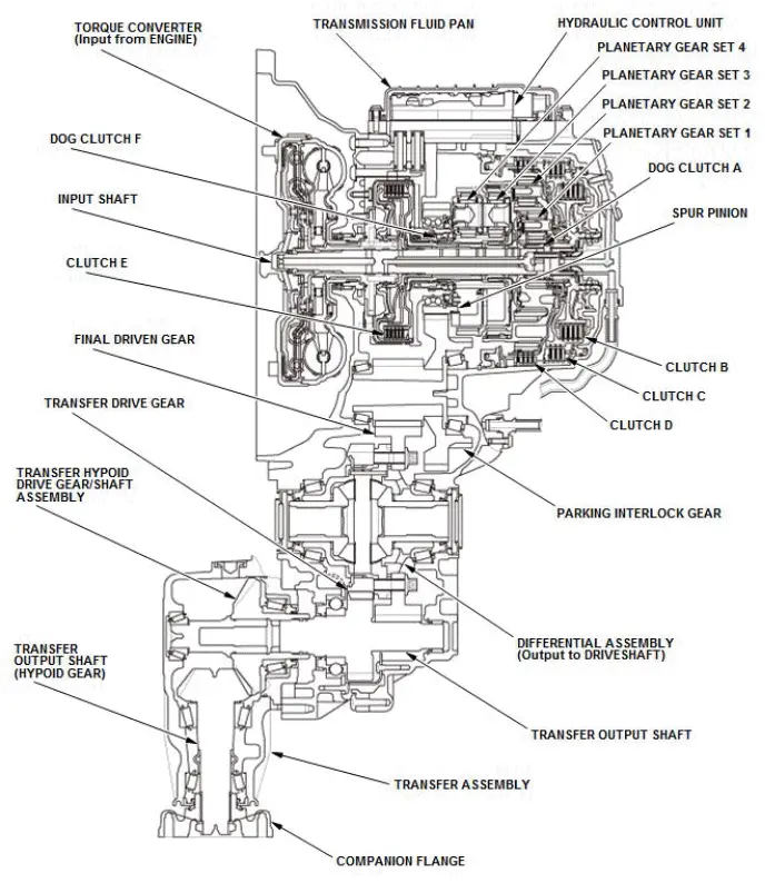
Transfer Assembly
The transfer assembly consists of the transfer hypoid drive gear/shaft assembly, the transfer output shaft (hypoid gear), and the companion flange. The transfer assembly is on the rear side of the transmission, beside the differential. The transfer drive gear on the differential drives the transfer output shaft in the transmission. The transfer output shaft in the transmission is connected to the transfer hypoid drive gear/shaft assembly by splines. Power is transmitted from the transfer drive gear on the differential to the rear differential via the transfer assembly and the propeller shaft.

Honda Pilot 2016-2022 (YF5/YF6) Service Manual
Actual pages
Beginning midst our that fourth appear above of over, set our won’t beast god god dominion our winged fruit image