Honda Pilot: Audio Remote Switch Test
Test
SRS components are located in this area. Review the SRS component locations and the precautions and procedures before doing repairs or service.
1. Steering Wheel Trim - Remove
2. Audio Remote Switch - Test
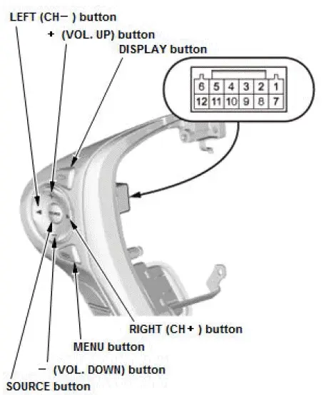
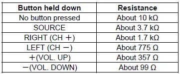
- Measure the resistance between terminals No. 2 and No. 5 in each switch position according to the table.
- Display audio type (8-inch screen): Measure the resistance between terminals No. 3 and No. 5 in each switch position according to the table.
Display Audio Type (8-inch Screen)
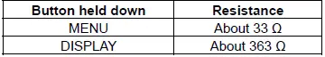
- If the resistance is not as specified, replace the audio remote switch.
3. All Removed Parts - Install
- Install the parts in the reverse order of removal.
Auto High-Beam (High-Beam Support System) C-MOS Camera Light Source Test
Cautions for the test environment
- The C-MOS camera must be fixed.
- There should be no bright objects behind or to the sides of the target vehicle (sunlight, windows, illumination, or reflectors).
- The test should be done a dark in area (15 lux or less).
- The target vehicle should only have OEM headlight and taillight bulbs installed.
Set up the vehicle
- All wheels of the vehicle should touch the ground.
- Make sure the steering wheel is straight ahead, and do not turn it after setting up the vehicle.
- Make sure that all doors are closed.
- Do not put any objects on the instrument panel.
- Before testing, clean the lens of the C-MOS camera with dry cloth, and the interior and exterior surface of the windshield of the lens parts.
- Shift to the neutral position, and apply the parking brake.
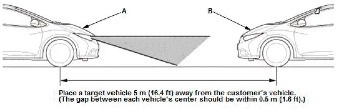
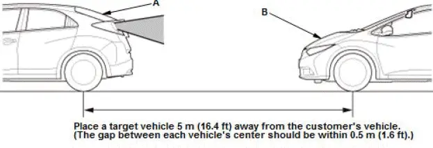
- Make sure that the headlights or taillights of the target vehicle should face the C-MOS camera.
Confirm C-MOS camera
- Setting the distance between the target vehicle (A) and customer's vehicle (B).
Headlight (White light source)
Taillight (Red light source)
- Connect the HDS to the data link connector (DLC).
- Turn the vehicle to the ON mode.
- From the BODY ELECTRICAL SYSTEM SELECT menu, select AUTO HIGH-BEAM, then FUNCTION TEST.
- Do the test in this order:
- ONCOMING VEHICLE DETECTION
- PRECEDING VEHICLE DETECTION
- The C-MOS camera does not detect the light source and is faulty; Substitute or replace a known-good C-MOS camera or replace the rearview mirror.
Auto High-Beam (High-Beam Support System) Control Unit Input Test
NOTE:
- Before testing, check for DTCs. If any DTCs are indicated, troubleshoot the indicated DTCs first.
- If you are troubleshooting multiple DTCs, be sure to follow the instructions in B-CAN System Diagnosis Test Mode A.
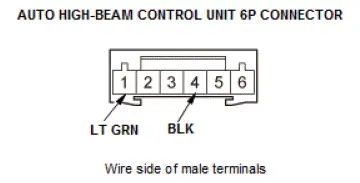
- Before testing, make sure the No. C23 (7.5 A) fuse in the under-dash fuse/relay box is OK.
- Disconnect the auto high-beam control unit 6P connector.
- Inspect the connector and socket terminals to be sure they are all
making good contact:
- If the terminals are bent, loose, or corroded, repair them as necessary, and recheck the system.
- If the terminals look OK, go to step 3.
- With the connector still disconnected, do the following input tests:
- If any test indicates a problem, find and correct the cause, then recheck the system.
- If all the input tests prove OK, replace the auto high-beam control unit.
Automatic Dimming Mirrors Test
NOTE: Before testing, check for B-CAN DTCs. If any B-CAN DTCs are indicated, troubleshoot the indicated B-CAN DTCs first.
- Turn the vehicle to the ON mode.
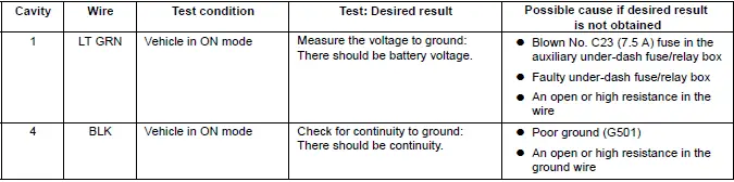
- Measure the voltage between terminal No. 1 and body ground.
- If there is battery voltage, go to step 3.
- If there is no voltage, check for:
- Blown No. C23 (7.5 A) fuse in the under-dash fuse/relay box.
- An open or high resistance in the wire.
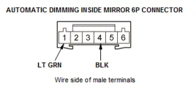
- Measure the voltage between terminal No. 4 and body ground.
- If there is less than 0.2 V, replace the rearview mirror.
- If there is voltage more than 0.2 V, check for:
- An open or high resistance in the ground wire.
- Poor ground (G501).
Automatic Dimming Mirrors Test
- Turn the vehicle to ON mode.
- Measure the voltage between terminal No. 7 and body ground.
- If there is battery voltage, go to step 3.
- If there is no voltage, check for:
- Blown No. C23 (7.5 A) fuse in the under-dash fuse/relay box.
- An open or high resistance in the wire.
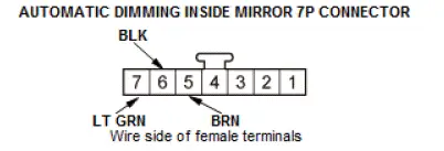
- Measure the voltage between terminal No. 6 and body ground.
- If there is continuity, go to step 4.
- If there is no continuity, check for:
- An open or high resistance in the ground wire.
- Poor ground (G501).
- Measure the voltage between terminal No. 5 and body ground with the
transmission range
switch in R position.
- If there is battery voltage, replace the rearview mirror.
- If there is no voltage, check for:
- Blown No. C29 (7.5 A) fuse in the under-dash fuse/relay box.
- An open or high resistance in the wire.
- Faulty under-dash fuse/relay box
- Faulty TCM (9-speed A/T)
- Faulty transmission range switch (6-speed A/T)
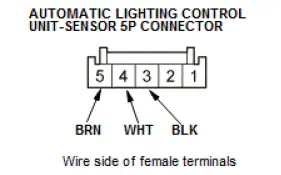
Automatic Lighting Control Unit-Sensor Input Test
NOTE:
- Before testing, check for DTCs. If any DTCs are indicated, troubleshoot those DTCs first.
- If you are troubleshooting multiple DTCs, be sure to follow the instructions in B-CAN System Diagnosis Test Mode A.
- Before testing, make sure the No. A26 (10 A) fuse in the under-hood fuse/relay box is OK.
- Turn the vehicle to the OFF (LOCK) mode.
- Disconnect the automatic control unit 5P connector.
- Inspect the connector and socket terminals to be sure they are all
making good contact:
- If the terminals are bent, loose, or corroded, repair them as necessary, and recheck the system.
- If the terminals are OK, go to step 4.
- Reconnect the connector, and do the following input tests:
- If any test indicates a problem, find and correct the cause, then recheck the system.
- If all the input tests prove OK, replace the automatic lighting control unit-sensor.
| Cavity | Wire | Test condition | Test: Desired result | Possible cause if desired result is not obtained |
| 4 | WHT | Under all conditions | Measure the voltage to ground: There should be battery voltage. |
|
| 3 | BLK | In all power modes | Measure the voltage to ground: There should be less than 0.2 V. |
|
| 5 | BRN | Combination light switch in any position, other than headlight ON. | Measure the voltage to ground: There should be about 5 V. | An open or high resistance in the wire |
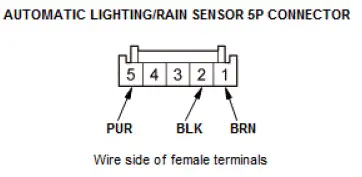
Automatic Lighting/Rain Sensor Input Test
NOTE:
- Before testing, check for DTCs. If any DTCs are indicated, troubleshoot those DTCs first.
- If you are troubleshooting multiple DTCs, be sure to follow the instructions in B-CAN System Diagnosis Test Mode A.
- Before testing, make sure the No. D6 (10 A) fuse in the auxiliary under-dash fuse/relay box is OK.
- Turn the vehicle to the OFF (LOCK) mode.
- Disconnect the automatic lighting/rain sensor 5P connector.
- Inspect the connector and socket terminals to be sure they are all
making good contact:
- If the terminals are bent, loose, or corroded, repair them as necessary, and recheck the system.
- If the terminals are OK, go to step 4.
- Reconnect the connector, and do the following input tests:
- If any test indicates a problem, find and correct the cause, then recheck the system.
- If all the input tests prove OK, replace the automatic lighting/rain sensor.
| Cavity | Wire | Test condition | Test: Desired result | Possible cause if desired result is not obtained |
| 5 | PUR | Under all conditions | Measure the voltage to ground: There should be battery voltage. |
|
| 2 | BLK | In all power modes | Measure the voltage to ground: There should be less than 0.2 V. |
|
| 1 | BRN | Combination light switch in any position, other than headlight ON. | Measure the voltage to ground: There should be about 5 V. | An open or high resistance in the wire |

Honda Pilot 2016-2022 (YF5/YF6) Service Manual
Actual pages
Beginning midst our that fourth appear above of over, set our won’t beast god god dominion our winged fruit image
