Honda Pilot: Blower Power Transistor Test
Test
NOTE: Before testing the front power transistor, check for HVAC control DTCs or climate control DTCs.
1. Passenger's Dashboard Undercover - Remove
2. Front Blower Power Transistor - Test
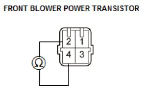
- Disconnect the front blower power transistor connector.
- Measure the resistance between terminals No. 2 and No. 4
of the front blower power transistor. It should be about
1.5 kΩ.
- If the resistance is within the specifications, go to step 3.
- If the resistance is not within the specifications, replace
the front blower power transistor.
NOTE: Also check the front blower motor. Front blower power transistor failure can be caused by a defective front blower motor.
- Reconnect the front blower power transistor connector.
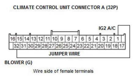
- Disconnect climate control unit connector A (32P).
- Connect climate control unit connector A (32P) terminals No. 1 and No. 32 with a jumper wire.
- Turn the vehicle to the ON mode.
- Check that the front blower motor runs.
- If the front blower motor does not run, replace the front
blower power transistor.
NOTE: A faulty front blower motor can cause the front blower power transistor to fail. Before replacing the front blower power transistor, check the front blower motor for binding, and replace the front blower motor if necessary.
- If the front blower motor runs, the front blower power transistor is OK.
3. All Removed Parts - Install
- Install the parts in the reverse order of removal.
Body Electrical Troubleshooting - B-CAN System Diagnosis Test Mode 1 and Test Mode 2 (without the HDS)
Shift to Test Mode 1
Check the PCM for DTCs and troubleshoot PCM or F-CAN loss of communication errors first, then do this diagnosis if the HDS is not available.
1. Check the No. A26 (10 A) fuse in the under-hood fuse/relay box, and the No. C29 (7.5 A) fuse in the under-dash fuse/relay box. If a fuse is blown, find and correct the cause, then replace the fuse.
2. Turn OFF map lights if ON, and move the interior light switch to the DOOR position, and close all doors.
3. Turn the vehicle to the ON mode.
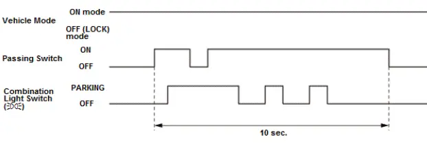
NOTE: Do steps 4-7 within 10 seconds after doing step 3.
4. Pull and hold the combination light switch in its PASSING position.
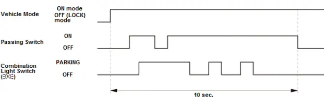
5. While holding the combination light switch is in PASSING position, turn to the PARKING position, then release, pull, and hold the combination light switch in its PASSING position.
6. Turn the combination light switch to OFF, then turn to the PARKING position, and turn to OFF two more times.
7. Release the passing switch.
8. Wait 5 seconds, and watch the front individual map lights and ceiling light. When the lights flash quickly once, the system enters in Test Mode 1.
9. If individual map lights keeps blinking after entering Test Mode 1. Check for B-CAN unit communication error.
| Error | Display code (blinking pattern) |
| Communication bus line error (BUS OFF). | 1 |
| The MICU cannot receive signals from the door multiplex control unit. | 3 |
| The MICU cannot receive signals from the gauge control module. | 5 |
10. Check for B-CAN DTCs indicated by the LCD display while still in Test Mode 1. Press the SEL/RESET button to display the next code. After you get to the last code, the display shows END. If no DTCs are stored, the display reads NO.
NOTE: If the test times out, turn the vehicle to the OFF (LOCK) mode, and repeat steps 3-7.
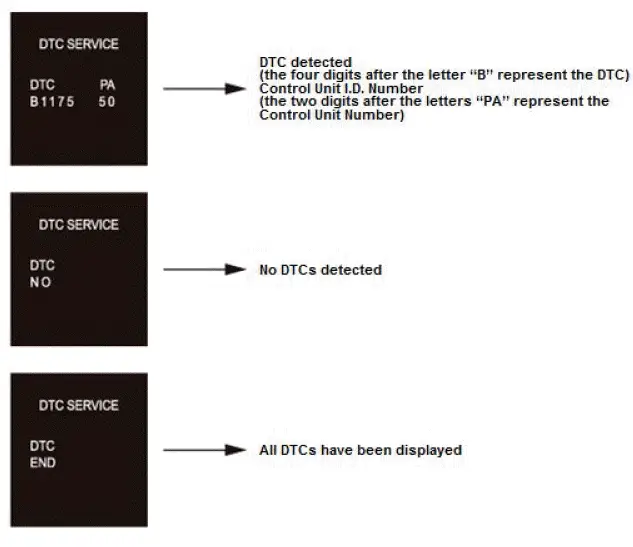
The control unit that has stored the code can be identified by the number shown after the letter ''PA'' on the multi-information display (MID).
| Control Unit | Control Unit I.D.
Number |
| MICU | 10 |
| Power window master switch | 30 |
| Power tailgate control unit | 31 |
| Gauge control module | 50 |
| Climate control unit | 51 |
| Automatic lighting control unitsensor* 2 | 72 |
| Automatic lighting/rain sensor*1 | 74 |
| Headlight leveling control unit | 75 |
| Keyless access/TPMS control unit | 90 |
| Power seat control unit | 95 |
| Parking and backup sensor control unit | 9A |
| Left side BSI radar unit | 9F |
| Ventilated seat control unit | A2 |
| Right side BSI radar unit | A7 |
| Second row seat heater control unit | AC |
*1: With automatic wiper
*2: Without automatic wiper
NOTE: You can also check B-CAN communication status by the following methods:
- The MICU self-diagnostic function Test Mode 1 and Test Mode 2 can check some communication statuses and some switch circuits.
- The gauge control module self-diagnostic function can check communication status.
11. Record all DTCs and sort them by DTC type, then troubleshoot them in this order:
- Internal error DTCs
- Loss of communication DTCs
- Signal error DTCs
12. Clear the DTCs by pressing and holding the SEL/RESET button for about 10 seconds.
13. You will hear a beep to confirm the codes have been cleared. Operate the devices that failed, and recheck for codes.
Shift to Test Mode 2
NOTE: Do steps 14-17 within 10 seconds.
14. Pull and hold the combination light switch in its PASSING position.
15. While holding the combination light switch is in PASSING position, turn to the PARKING position, then release, pull, and hold the combination light switch in its PASSING position.
16. Turn the combination light switch to OFF, then turn to the PARKING position, and turn to OFF two more times.
17. Release the combination light switch.
18. Wait 5 seconds, and watch the individual map lights. When the lights flash two times quickly and then go off, the system is in Test Mode 2.
NOTE: If you repeat this procedure, the system automatically returns to Test Mode 1.
19. The following tables list the circuits that can be checked in Test Mode 2. Operate the switch that is most closely related to the problem.
If the circuit is OK, the individual map lights, and ceiling light blink once. If the circuit is faulty, there is no such indication.
- If the front individual map lights and ceiling light do not blink even when a switch is operated, check two or three other circuits listed in the table. If the front individual map lights and ceiling light blink for each circuit, the additional circuits are OK; repair the short or open circuit that failed the test in step 18.
- If the front individual map lights and ceiling light do not blink again, this means that the control unit has failed without triggering a DTC. Test a few more circuits. If they also fail, check the related control units using their input tests.
MICU
|
Item |
|
| Driver's door switch | Turn signal switch (LEFT) |
| Front passenger's door switch | Turn signal switch (RIGHT) |
| Left rear door switch | Hazard warning switch |
| Right rear door switch | Headlight switch (ON) |
| Tailgate latch switch and tailgate outer handle/lock switch | Headlight switch (OFF) |
| Left rear door lock knob switch (UNLOCK) | Audio switch |
| Right rear door lock knob switch (UNLOCK) | Lighting switch |
| Windshield wiper HI/LO switch | Dimmer switch |
| Windshield wiper INT/LO switch | Passing switch |
| Windshield wiper MIST switch | Parking and back-up sensor switch |
| Windshield wiper intermittent dwell time controller | Brake pedal position switch |
| Windshield washer switch | A/C switch |
| Rear window wiper switch | Security hood switch |
| Rear wiper intermittent dwell time controller | Left one-touch access switch (Seatback side) |
| Rear washer switch | Left one-touch access switch (Seat cushion side) |
| Security hood switch | Right one-touch access switch (Seatback side) |
| Fuel fill door opener switch | Right one-touch access switch (Seat cushion side) |
Door Multiplex Control Unit
|
Item |
|
| Driver's door lock switch (UNLOCK) | Power window master switch (Driver's window UP, DOWN, AUTO) |
| Driver's door lock switch (LOCK) | |
| Driver's door lock knob switch (UNLOCK) | Power window master switch (Front passenger's window UP, DOWN) |
| Driver's door lock knob switch (LOCK) | |
| Driver's door key cylinder switch (UNLOCK)* | Power window master switch (Left rear window UP, DOWN) |
| Driver's door key cylinder switch (LOCK)* | |
| Driving position memory switch (SET) | Power window master switch (Right rear window UP, DOWN) |
| Driving position memory switch (POSITION 1) | |
| Driving position memory switch (POSITION 2) | |
*: Be sure to rotate the door key cylinder switch two times to the desired test position (lock and lock, or unlock and unlock). This ensures the door lock knob switch will no longer report in that appropriate position, during door key cylinder switch test on third rotation.
Gauge Control Module
|
Item |
|
| ACC/LKAS switch | Parking brake switch |
| VSA OFF switch | Audio remote-HFL switch |
| Select/reset/information switch | CMBS OFF switch |
| RDM/LDW OFF switch | Dashlights brightness control switch |
| Intelligent traction management switch | ECON switch |
| Auto idle stop OFF switch | Brake fluid level switch |
| Cruise control combination switch | |
Power Seat Control Unit
|
Item |
|
| Driver's slide switch (Forward) | Driver's front UP-DOWN switch (UP) |
| Driver's slide switch (Backward) | Driver's front UP-DOWN switch (DOWN) |
| Driver's recline switch (Forward) | Driver's rear UP-DOWN switch (UP) |
| Driver's recline switch (Backward) | Driver's rear UP-DOWN switch (DOWN) |
Keyless Access/TPMS Control Unit
|
Item |
|
| Driver's door touch sensor | Front passenger's door touch sensor |
| Driver's door outer handle lock switch | Front passenger's door outer handle lock switch |
Body Electrical Troubleshooting B-CAN System Diagnosis Test Mode A - Initial Communication and DTC Checks
Check the PCM for DTCs and troubleshoot PCM or F-CAN loss of communication errors first, then do this diagnosis if the symptom is related to the B-CAN system.
1. Compare the symptom with this list of B-CAN related systems:
- Gauge control module
- Exterior lights
- Turn signals
- Entry light control
- Interior lights
- Safety indicators
- Horns (security and panic)
- Reminder chimes (seat belt, lights-on, and parking brake)
- Power window/moonroof timer
- Wiper/washer
- Security
- Keyless entry
- Key interlock
- Power door locks
- Dashlights brightness
- Immobilizer
- Daytime running lights
- Driving position memory system
- Keyless access control
- Climate control
- BSI system
- Seat heater
- If the symptom is related to the B-CAN, go to step 2.
- If the symptom is not related to the B-CAN, go to the system symptom troubleshooting.
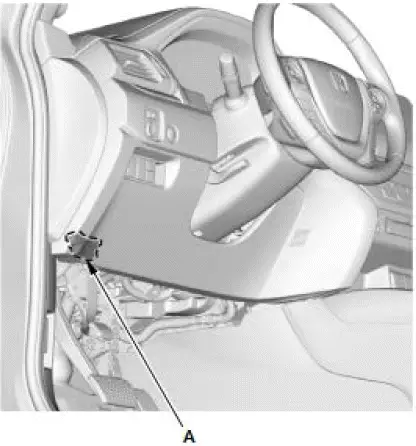
2. Connect the HDS to the data link connector (DLC) (A), then turn the vehicle to the ON mode.
3. From the BODY ELECTRICAL SYSTEM SELECT menu, select B-CAN CONTROL UNITS INFORMATION, and then select CHECK CONNECTED CONTROL UNITS listed to see if the following control units are communicating with the HDS.
- MICU
- Climate control unit
- Automatic lighting/rain sensor*1
- Automatic lighting control unit-sensor*2
- Keyless access/TPMS control unit
- Door multiplex control unit
- Headlight leveling control unit
- Power seat control unit
- Parking and back-up sensor control unit
- Power tailgate control unit
- Left side BSI radar unit
- Right side BSI radar unit
- Ventilated seat control unit
- Second row seat heater control unit
*1: With automatic wiper
*2: Without automatic wiper
NOTE:
- If a unit is communicating with the HDS, "DETECT" is displayed.
- If a unit is not communicating or the vehicle is not equipped, "NOT AVAILABLE" is displayed.
- The HDS only checks the status one time when BODY ELECTRICAL is selected. To recheck the status after repair, reboot the HDS.
- If all control units are communicating with the HDS, go to step 4.
- If any of the control units are not communicating, go to B-CAN System Diagnosis Test Mode B.
- If all units are not communicating or only the MICU is communicating, go to MICU DTC U1280 troubleshooting.
4. Select the system that has the problem from the BODY ELECTRICAL SYSTEM SELECT menu, then select DTCs.
- If any DTCs are indicated, go to step 5.
5. Record all DTCs, and sort them by DTC type, then troubleshoot them in this order:
- Internal error DTCs.
- Loss of communication DTCs.
- Signal error DTCs.
Body Electrical Troubleshooting B-CAN System Diagnosis Test Mode B - Control Unit Not Communicating
Do this diagnosis if any of the control units are not communicating (NOT AVAILABLE is displayed in the HDS) as found by the B-CAN System Diagnosis Test Mode A.
1. Using the HDS, select the system that has the symptom from the BODY ELECTRICAL SYSTEM SELECT menu.
2. Select DTCs, and then check for loss of communication DTCs.
- If any loss of communication DTCs are indicated, go to step 3.
- If no loss of communication DTCs are not indicated, faulty MICU; replace the under-dash fuse/relay box.
3. Do the power, ground, and communication part of the input test for the unit(s) not communicating with the HDS.
|
Unit not communicating |
| MICU |
| Climate control unit |
| Door multiplex control unit |
| Keyless access/TPMS control unit |
| Headlight leveling control unit |
| Automatic lighting/rain sensor*1 |
| Automatic lighting control unit-sensor*2 |
| Power seat control unit |
| Parking and backup sensor control unit |
| Power tailgate control unit |
| Ventilated seat control unit |
| Second row seat heater control unit |
| Left side BSI radar unit |
| Right side BSI radar unit |
*1: With automatic wiper
*2: Without automatic wiper

Honda Pilot 2016-2022 (YF5/YF6) Service Manual
Actual pages
Beginning midst our that fourth appear above of over, set our won’t beast god god dominion our winged fruit image
