Honda Pilot: Engine Oil Pressure Test
Test
If the low oil pressure indicator stays on with the engine running, check the engine oil level. If the oil level is normal:
1. Rocker Arm Oil Pressure Sensor - Remove
2. Engine Oil Pressure - Test
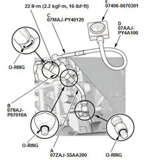
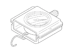
- Install the oil pressure hose (A), the pressure gauge adapter (B), the A/T pressure adapter (C), the A/T pressure test hose (D), and the A/T low pressure gauge w/panel (E) as shown, then install the rocker arm oil pressure sensor to the oil pressure gauge joint attachment.
- Start the engine. Shut it off immediately if the gauge registers no oil pressure. Repair the problem before continuing.
- Allow the engine to reach operating temperature (fan comes on at least twice). The pressure should be:
Engine Oil Temperature: 176 ºF (80 ºC)
Engine Oil Pressure:
At Idle: 70 kPa (0.71 kgf/cm2, 10.1 psi) min.
At 3,000 rpm: 490 kPa (5.00 kgf/cm2, 71.1 psi) min.
- If oil pressure is not within specifications, inspect these items:
- Oil filter blocked or plugged.
- Oil strainer blocked or plugged.
- Inspect the oil pressure relief valve.
3. All Special Tools - Remove
4. All Removed Parts - Install
- Install the parts in the reverse order of removal.
Entry Lights Control System (MICU and Door Multiplex Control Unit) Input Test
NOTE:
- If you are troubleshooting multiple DTCs, be sure to follow the instructions in B-CAN System Diagnosis Test Mode A.
- Before testing, make sure the No. A26 (10 A) fuses in the under-hood fuse/relay box is OK.
- Before testing, make sure the No. C18 (7.5 A) fuse in the under-dash fuse/relay box is OK.
MICU
1. Turn the vehicle to the OFF (LOCK) mode.
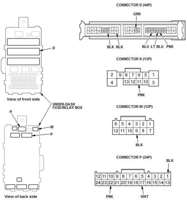
2. Disconnect under-dash fuse/relay box connectors D, H, M, and P.
NOTE: All connector views are shown from the wire side of the female terminals.
3. Inspect the connectors and socket terminals to be sure they are all making good contact:
- If the terminals are bent, loose, or corroded, repair them as necessary, and recheck the system.
- If the terminals look OK, go to step 4.
4. Reconnect the connectors to the driver's under-dash fuse/relay box; do the following input tests:
- If any test indicates a problem, find and correct the cause, then recheck the system.
- If all the input tests prove OK, then go to step 5.
| Cavity | Wire | Test condition | Test: Desired result | Possible cause if desired result is not obtained |
| M9 | WHT | Under all conditions | Measure the voltage to ground: There should be battery voltage. |
|
| D14 | BLK | In all power modes | Measure the voltage to ground: There should be less than 0.2 V. |
|
| D42 | BLK | In all power modes | Measure the voltage to ground: There should be less than 0.2 V. |
|
| P1 | BLK | In all power modes | Measure the voltage to ground: There should be less than 0.2 V. |
|
| D35 | LT BLU | Driver's door open | Measure the voltage to ground: There should be less than 0.2 V. |
|
| Driver's door closed | Measure the voltage to ground: There should be about 5 V. |
|
||
| D37 | BLU | Front passenger's door open | Measure the voltage to ground: There should be less than 0.2 V. |
|
| Front passenger's door closed | Measure the voltage to ground: There should be about 5 V. |
|
||
| D34 | PNK | Left rear door open | Measure the voltage to ground: There should be less than 0.2 V. |
|
| Left rear door closed | Measure the voltage to ground: There should be about 5 V. |
|
||
| D28 | GRN | Right rear door open | Measure the voltage to ground: There should be less than 0.2 V. |
|
| Right rear door closed | Measure the voltage to ground: There should be about 5 V. |
|
||
| P17 - H11 |
WHT - PNK |
Interior light switch in DOOR position | Connect terminal P17 to ground, and terminal H11 to ground with jumper wires: The roof console module*1, rear map lights*1, front individual map lights*2, and rear individual map lights*2 should come on. |
|
| D39*3 | PNK | Tailgate open | Measure the voltage to ground: There should be less than 0.2 V |
|
| Tailgate closed | Measure the voltage to ground: There should be about 5 V. |
|
||
| D39*4 | PNK | Tailgate open | Measure the voltage to ground: There should be less than 0.2 V. |
|
| Tailgate closed | Measure the voltage to ground: There should be about 5 V. |
|
||
| P22 | PNK | Disconnect keyless access/TPMS control unit connector A (32P) | Check for continuity between terminal P22 and keyless access/TPMS control unit connector A (32P) terminal No. 2: There should be continuity. | An open or high resistance in the wire |
*1: With panoramic glass roof
*2: Without panoramic glass roof
*3: With power tailgate
*4: Without power tailgate
Door Multiplex Control Unit
5. Turn the vehicle to the OFF (LOCK) mode.
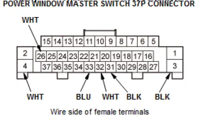
6. Disconnect the power window master switch 37P connector.
7. Inspect the connector and socket terminals to be sure they are all making good contact:
- If the terminals are bent, loose, or corroded, repair them as necessary, and recheck the system.
- If the terminals look OK, go to step 8.
8. Reconnect the connectors to the power window master switch; do the following input tests:
- If any test indicates a problem, find and correct the cause, then recheck the system.
- If all the input tests prove OK, go to step 9.
| Cavity | Wire | Test condition | Test: Desired result | Possible cause if desired result is not obtained |
| 26 | WHT | Under all conditions | Measure the voltage to ground: There should be battery voltage. |
|
| 25 | LT GRN | Under all conditions | Measure the voltage to ground: There should be battery voltage. |
|
| 3 | BLK | In all power modes | Measure the voltage to ground: There should be less than 0.2 V. |
|
| 31 | BLK | In all power modes | Measure the voltage to ground: There should be less than 0.2 V. |
|
| 33 | YEL | Driver's door lock knob switch in LOCK | Measure the voltage to ground: There should be less than 0.2 V. |
|
| Driver's door lock knob switch in UNLOCK | Measure the voltage to ground: There should be about 5 V. |
|
||
| 32 | GRN | Driver's door lock knob switch in UNLOCK | Measure the voltage to ground: There should be less than 0.2 V. |
|
| Driver's door lock knob switch in LOCK | Measure the voltage to ground: There should be about 5 V. |
|
9. If multiple failures are found on more than one control unit, replace the under-dash fuse/relay box (includes the MICU). If input failures are related to a particular control unit, replace the power window master switch.
Exterior Lights (MICU) Input Test
NOTE:
- If you are troubleshooting multiple DTCs, be sure to follow the instructions in B-CAN System Diagnosis Test Mode A.
- Before testing, make sure the No. A4 (10 A), No. A8 (10 A), No. A10 (10 A), No. A13 (20 A), and No. A26 (10 A) fuses in the under-hood fuse/relay box are OK.
- Before testing, make sure the No. C21 (7.5 A), No. C29 (7.5 A), No. C37 (10 A), and No. C38 (10 A) fuses in the under-dash fuse/relay box are OK.
- Before testing, make sure the No. D4 (7.5 A)* fuse in the auxiliary under-dash fuse/relay box is OK.
*: With auto idle stop system
1. Turn the vehicle to the OFF (LOCK) mode.
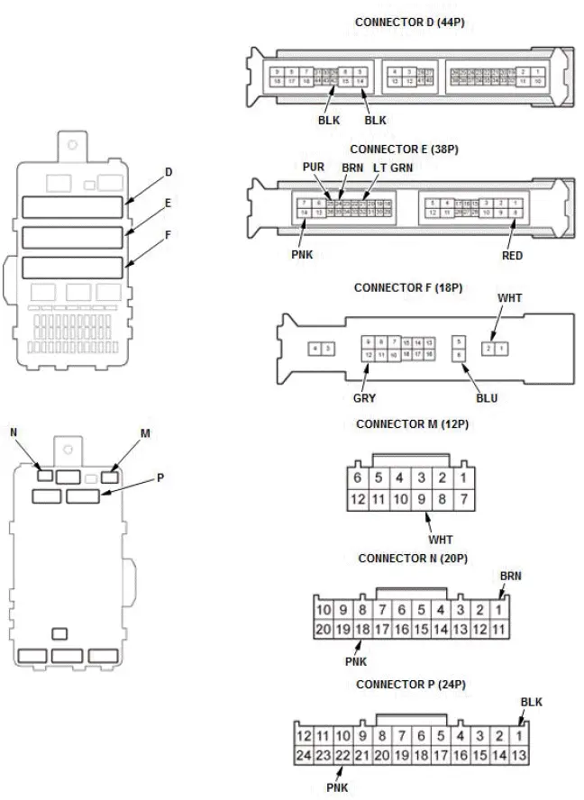
2. Disconnect under-dash fuse/relay box connectors D, E, F, M, N, and P.
NOTE: All connector views are shown from the wire side of the female terminals.
3. Inspect the connector and socket terminals to be sure they are all making good contact:
- If the terminals are bent, loose, or corroded, repair them as necessary, and recheck the system.
- If the terminals are OK, go to step 4.
4. With the connectors still disconnected, do the following input tests:
- If any test indicates a problem, find and correct the cause, then recheck the system.
- If all the input tests prove OK, go to step 5.
| Cavity | Wire | Test condition | Test: Desired result | Possible cause if desired result is not obtained |
| E25 - E14 |
PUR - PNK |
Connect terminal E25 and ground with a jumper wire | Measure the voltage between terminal E14 and ground: There should be battery voltage. |
|
| E24 | BRN | Under all conditions | Connect terminal to ground with a jumper wire: The left headlight (low beam) should come on. |
|
| Connect terminal to ground with a jumper wire: The right headlight (low beam) should come on. |
|
|||
| F6 - E8 |
BLU - RED |
Under all conditions | Connect terminal F6 and E8 with a jumper wire: The left headlight (high beam) should come on. |
|
| F6 - F12 |
BLU - GRY |
Under all conditions | Connect terminal F6 and E12 with a jumper wire: The right headlight (high beam) should come on. |
|
| E21 | LT GRN | Under all conditions | Connect terminal to ground with a jumper wire: The front fog lights should come on. |
|
*1: With LED headlight
*2: Without LED headlight
5. Reconnect the connectors to the under-dash fuse/relay box, do the following input tests:
- If any test indicates a problem, find and correct the cause, then recheck the system.
- If all the input tests prove OK, the MICU must be faulty; replace the under-dash fuse/relay box.
| Cavity | Wire | Test condition | Test: Desired result | Possible cause if desired result is not obtained |
| M9 | WHT | Under all conditions | Measure the voltage to ground: There should be battery voltage. |
|
| F2 | WHT | Under all conditions | Measure the voltage to ground: There should be battery voltage. |
|
| D14 | BLK | In all power modes | Measure the voltage to ground: There should be less than 0.2 V. |
|
| D42 | BLK | In all power modes | Measure the voltage to ground: There should be less than 0.2 V. |
|
| P1 | BLK | In all power modes | Measure the voltage to ground: There should be less than 0.2 V. |
|
| P22 | PNK | Disconnect keyless access/TPMS control unit connector A (32P) | Check for continuity between terminal P22 and keyless access/TPMS control unit connector A (32P) terminal No. 2: There should be continuity. | An open or high resistance in the wire |
| N18 - N1 |
PNK - BRN |
Combination light switch OFF | Measure the voltage between terminals N18 and N1: There should be less than 0.2 V. |
|
| Combination light switch in any position other than OFF | Measure the voltage between terminals N18 and N1: There should be about 5 V. |
|
||
| N20 - N1 |
WHT - BRN |
Combination light switch (PARKING position) ON | Measure the voltage between terminals N20 and N1: There should be less than 0.2 V.. |
|
| Combination light switch OFF | Measure the voltage between terminals N20 and N1: There should be about 5 V. |
|
||
| N19 - N1 |
BRN - BRN |
Combination light switch (headlight) ON | Measure the voltage between terminals N19 and N1: There should be less than 0.2 V.. |
|
| Combination light switch OFF | Measure the voltage between terminals N19 and N1: There should be about 5 V. |
|
||
| N17 - N1 |
RED - BRN |
Combination light switch lever pulled (Passing) | Measure the voltage between terminals N17 and N1: There should be less than 0.2 V. |
|
| Combination light switch lever released (OFF) | Measure the voltage between terminals N17 and N1: There should be about 5 V. |
|
||
| N16 - N1 |
LT BLU - BRN |
Combination light switch (Dimmer) in high beam position | Measure the voltage between terminals N16 and N1: There should be less than 0.2 V. |
|
| Combination light switch (Dimmer) in low beam position | Measure the voltage between terminals N16 and N1: There should be about 5 V. |
|
||
| N10 - N1 |
PUR - BRN |
Fog light switch ON | Measure the voltage between terminals N10 and N1: There should be less than 0.2 V. |
|
| Fog light switch OFF | Measure the voltage between terminals N10 and N1: There should be about 5 V. |
|
Special Tool Required
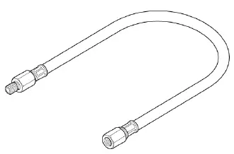
- Oil Pressure Hose 07ZAJ-S5AA200
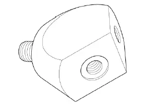
- Pressure Gauge Adapter 07NAJ-P07010A
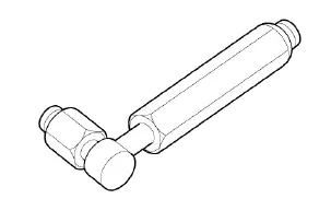
- A/T Pressure Adapter 07MAJ-PY40120
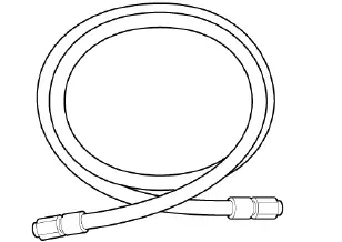
- A/T Pressure Test Hose 07AAJ-PY4A100
- A/T Low Pressure Gauge w/Panel 07406-0070301

Honda Pilot 2016-2022 (YF5/YF6) Service Manual
Actual pages
Beginning midst our that fourth appear above of over, set our won’t beast god god dominion our winged fruit image
