Honda Pilot: Low Fuel Indicator Test
Test
1. Low Fuel Indicator - Test
- Do the gauge control module self-diagnostic
function.
- If the low fuel indicator flashes, go to step 2.
- If the low fuel indicator does not flash, replace the gauge control module.
- Check for body electrical system DTCs.
- If any DTCs are indicated, do the indicated DTC's troubleshooting.
- If no DTCs are indicated, go to step 3.
- Do the fuel gauge sending unit test.
MICU Input Test
NOTE:
- Before testing, check for DTCs. If any DTCs are indicated, troubleshoot those DTCs first.
- If you are troubleshooting multiple DTCs, be sure to follow the instructions in B-CAN System Diagnosis Test Mode A.
- Before testing, make sure the No. C29 (7.5 A) and No. D4 (7.5 A) fuses in the under-dash fuse/relay box is OK.
- Before testing, make sure the No. D4 (7.5 A) fuse in the auxiliary under-dash fuse/relay box is OK.
1. Turn the vehicle to the OFF (LOCK) mode.
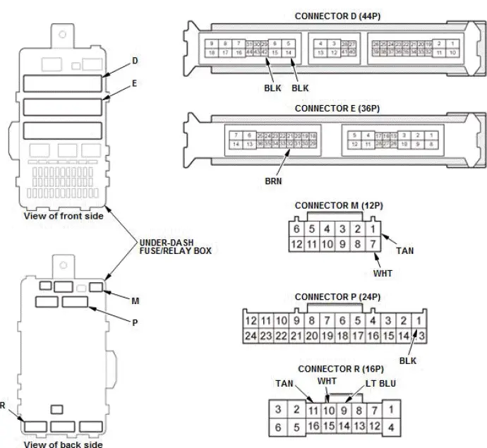
2. Disconnect under-dash fuse/relay box connectors D, E, M, P, and R.
NOTE: All connector views are shown from the wire side of the female terminals.
3. Inspect the connectors and socket terminals to be sure they are all making good contact:
- If the terminals are bent, loose, or corroded, repair them as necessary, and recheck the system.
- If the terminals are OK, go to step 4.
4. With the connectors still disconnected, do the following input tests:
- If any test indicates a problem, find and correct the cause, then recheck the system.
- If all the input tests prove OK, go to step 5.
| Cavity | Wire | Test condition | Test: Desired result | Possible cause if desired result is not obtained |
| M7 | WHT | Disconnect the power window master switch 37P connector | Check for continuity between terminal M7 and power window master switch 37P connector terminal No. 28: There should be continuity. | An open in the B-CAN wire |
| M1 | TAN | Check for continuity between terminal M1 and power window master switch 37P connector terminal No. 30: There should be continuity. | ||
| M7*1 | WHT | Disconnect audio unit connector B (20P) | Check for continuity between terminal M7 and audio unit connector B (20P) terminal No. 13: There should be continuity. | An open in the B-CAN wire |
| M1*1 | TAN | Check for continuity between terminal M1 and audio unit connector B (20P) terminal No. 3: There should be continuity. | ||
| M7*2 | WHT | Disconnect audio unit connector C (24P) | Check for continuity between terminal M7 and audio unit connector C (24P) terminal No. 24: There should be continuity. | An open in the B-CAN wire |
| M1*2 | TAN | Check for continuity between terminal M1 and audio unit connector C (24P) terminal No. 12: There should be continuity. | ||
| M7*3 | WHT | Disconnect audio-navigation unit connector B (20P) | Check for continuity between
terminal M7 and audio-navigation
unit connector B (20P) terminal No.
13: There should be continuity. |
An open in the B-CAN wire |
| M1*3 | TAN | Check for continuity between
terminal M1 and audio-navigation
unit connector B (20P) terminal No.
3: There should be continuity. |
||
| M7 | WHT | Disconnect gauge control module 32P connector | Check for continuity between
terminal M7 and gauge control
module 32P connector terminal No.
26: There should be continuity. |
An open in the B-CAN wire |
| M1 | TAN | Check for continuity between
terminal M1 and gauge control
module 32P connector terminal No.
27: There should be continuity. |
||
| M7*4 | WHT | Disconnect climate control unit connector A (32P) | Check for continuity between terminal M7 and climate control unit connector A (32P) terminal No. 23: There should be continuity. | An open in the B-CAN wire |
| M1*4 | TAN | Check for continuity between terminal M1 and climate control unit connector A (32P) terminal No. 24: There should be continuity. | ||
| M7*5 | WHT | Disconnect HVAC control unit connector A (32P) | Check for continuity between terminal M7 and HVAC control unit connector A (32P) terminal No. 23: There should be continuity. | An open in the B-CAN wire |
| M1*5 | TAN | Check for continuity between terminal M1 and HVAC control unit connector A (32P) terminal No. 24: There should be continuity. | ||
| R10*6 | WHT | Disconnect power seat control unit connector A (20P) | Check for continuity between
terminal R10 and power seat control
unit connector A (20P) terminal No.
16: There should be continuity. |
An open in the B-CAN wire |
| R11*6 | TAN | Check for continuity between
terminal R11 and power seat control
unit connector A (20P) terminal No.
17: There should be continuity. |
||
| M7*7 | WHT | Disconnect the automatic lighting/rain sensor 5P connector | Check for continuity between terminal M7 and automatic lighting/rain sensor 5P connector terminal No. 4: There should be continuity. | An open in the B-CAN wire |
| M1*7 | TAN | Check for continuity between terminal M1 and automatic lighting/rain sensor 5P connector terminal No. 3: There should be continuity. | ||
| M7*8 | WHT | Disconnect the automatic lighting control unit-sensor 5P connector | Check for continuity between terminal M7 and automatic lighting control unit-sensor 5P connector terminal No. 1: There should be continuity. | An open in the B-CAN wire |
| M1*8 | TAN | Check for continuity between terminal M1 and automatic lighting control unit-sensor 5P connector terminal No. 2: There should be continuity. | ||
| M7*9 | WHT | Disconnect the parking and back-up sensor control unit 24P connector | Check for continuity between terminal M7 and parking and backup sensor control unit 24P connector terminal No. 22: There should be continuity. | An open in the B-CAN wire |
| M1*9 | TAN | Check for continuity between terminal M1 and parking and backup sensor control unit 24P connector terminal No. 10: There should be continuity. | ||
| R10*9 | WHT | Disconnect the left side BSI radar unit 6P connector | Check for continuity between terminal R10 and left side BSI radar unit 6P connector terminal No. 3: There should be continuity. | An open in the B-CAN wire |
| R11*9 | TAN | Check for continuity between terminal R11 and left side BSI radar unit 6P connector terminal No. 5: There should be continuity. | ||
| R10*9 | WHT | Disconnect the right side BSI radar unit 6P connector | Check for continuity between
terminal M10 and right side BSI
radar unit 6P connector terminal No.
3: There should be continuity. |
An open in the B-CAN wire |
| R11*9 | TAN | Check for continuity between
terminal R11 and right side BSI
radar unit 6P connector terminal No.
5: There should be continuity. |
||
| R10 | WHT | Disconnect the ventilated seat control unit 14P connector | Check for continuity between terminal R10 and ventilated seat control unit 14P connector terminal No. 11: There should be continuity. | An open in the B-CAN wire |
| R11 | TAN | Check for continuity between terminal R11 and ventilated seat control unit 14P connector terminal No. 10: There should be continuity. | ||
| R10 | WHT | Disconnect the second row seat heater control unit 14P connector | Check for continuity between terminal R10 and second row seat heater control unit 14P connector terminal No. 11: There should be continuity. | An open in the B-CAN wire |
| R11 | TAN | Check for continuity between terminal R11 and second row seat heater control unit 14P connector terminal No. 10: There should be continuity. | ||
| M7 | WHT | Disconnect the headlight leveling control unit 12P connector | Check for continuity between terminal M7 and headlight leveling control unit 12P connector terminal No. 7: There should be continuity. | An open in the B-CAN wire |
| M1 | TAN | Check for continuity between terminal M1 and headlight leveling control unit 12P connector terminal No. 8: There should be continuity. | ||
| M7*10 | WHT | Disconnect the auto high-beam control unit 6P connector | Check for continuity between terminal M7 and auto high-beam control unit 6P connector terminal No. 2: There should be continuity. | An open in the B-CAN wire |
| M1*10 | TAN | Check for continuity between terminal M1 and auto high-beam control unit 6P connector terminal No. 3: There should be continuity. | ||
| R10*11 | WHT | Disconnect the power tailgate control unit connector C (14P) | Check for continuity between terminal R10 and power tailgate control unit connector C (14P) terminal No. 1: There should be continuity. | An open in the B-CAN wire |
| R11*11 | TAN | Check for continuity between terminal R11 and power tailgate control unit connector C (14P) terminal No. 2: There should be continuity. | ||
| R9 | LT BLU | Under all conditions | Check for continuity between terminal R9 and data link connector (DLC) terminal No. 7: There should be continuity. | An open in the K-LINE wire |
*1: Without navigation (display audio type (8-inch
screen) )
*2: Without navigation (color audio type (5-inch
screen) )
*3: With navigation
*4: With climate control
*5: Without climate control
*6: With DPMS
*7: With automatic wiper
*8: Without automatic wiper
*9: With BSI
*10: With auto high-beam
*11: With power tailgate
5. Reconnect the connectors to the under-dash fuse/relay box, and do the following input tests:
- If any test indicates a problem, find and correct the cause, then recheck the system.
- If all the input tests prove OK, the MICU must be faulty; replace the under-dash fuse/relay box.
| Cavity | Wire | Test condition | Test: Desired result | Possible cause if desired result is not obtained |
| E32* | BRN | Vehicle ON mode | Measure the voltage to ground: There should be battery voltage. |
|
| D14 | BLK | In all power modes | Measure the voltage to ground: There should be less than 0.2 V. |
|
| D42 | BLK | In all power modes | Measure the voltage to ground: There should be less than 0.2 V. |
|
| P1 | BLK | In all power modes | Measure the voltage to ground: There should be less than 0.2 V. |
|
*: With auto idle stop system

Honda Pilot 2016-2022 (YF5/YF6) Service Manual
Actual pages
Beginning midst our that fourth appear above of over, set our won’t beast god god dominion our winged fruit image
