Honda Pilot: Panoramic Glass Roof Sunshade Trim Removal and Installation
Removal/Installation
NOTE: SRS components are located in this area. Review the SRS component locations and the precautions and procedures before doing repairs or service.
1. Headliner - Remove
2. Sunshade Frame - Remove
3. Sunshade Trim - Remove
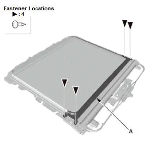
- Remove the rear sunshade trim (A).
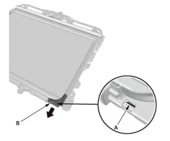
- Release the hook (A), and then remove the front sunshade trim (B).
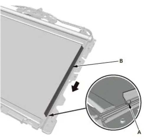
- Release the hook (A), and then remove the side sunshade trim (B).
4. All Removed Parts - Install
- Install the parts in the reverse order of removal.
Parasitic Draw Check
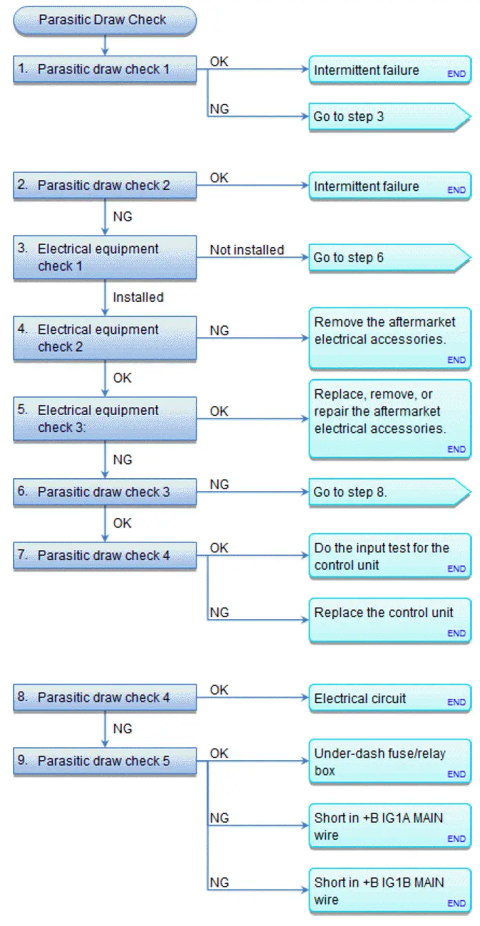
Parasitic Draw Check
Special Tools Required
LH41 AC/DC low current clamp meter, FLULH41A*
*: Available through the Acura Tool and Equipment Program, 888-424-6857
1. Parasitic draw check 1:
- Make sure the 12 volt battery is fully charged, and that all the vehicle's electrical accessories are turned off.
- To make the security alarm system recognize that the door is closed, open the hood, and disconnect the security hood switch 2P connector from the hood latch.
- Connect the security hood switch 2P connector terminals No. 1 and No. 2 with a jumper wire.
- Turn the vehicle to the ON mode.
- Turn the vehicle to the OFF (LOCK) mode.
- Get out of the vehicle, and close all doors and tailgate securely.
- Lock the doors with the keyless remote.
- Make sure the individual map lights are turned off, and the security alarm system is armed.
- Wait for at least 20 minutes.
-
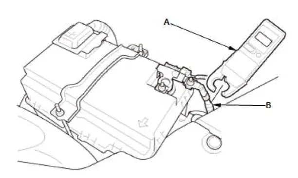
Attach the LH41 AC/DC low current clamp meter (A) to the 12 volt battery ground cable (B). Follow the equipment
manufacturer's instructions, then measure the parasitic draw.
NOTE: If you are using a digital multimeter: go to step 2.
Is the parasitic draw 27 mA or less?
 Intermittent failure, the system is normal at this time.
 Go to step 3.
2. Parasitic draw check 2:
NOTE: If LH AC/DC low current clamp meter (FLULH41A) is not available, do the follow procedure with a digital multimeter.
- Check the following items before measuring:
- During the procedure, do not depress the brake pedal, when you are prompted to turn the vehicle ON. Otherwise the vehicle will attempt to start and will blow the fuse in your digital multimeter.
- Set the multimeter dial to the DCA (direct current amps) range.
- Plug the red test probe into the red A (Amps) jack, and plug the black test probe into the COM jack.
- To avoid blowing an input fuse, start by setting the range above 10 A.
- Make sure the 12 volt battery is fully charged, and that all the vehicle's electrical accessories are turned off.
- To make the security alarm system recognize that the door is closed, open the hood, and disconnect the security hood switch 2P connector.
- Connect the security hood switch 2P connector terminals No. 1 and No. 2 with a jumper wire.
- Turn the vehicle to the ON mode.
- Turn the vehicle to the OFF (LOCK) mode.
- Get out of the vehicle, and close all doors and tailgate securely.
- Lock the doors with the keyless remote.
- Make sure the individual map lights are turned off, and the security alarm system is armed.
- Wait for at least 20 minutes.
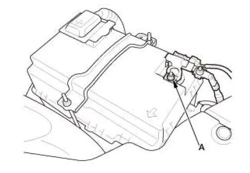
- Loosen the nut (A) on the 12 volt battery negative terminal.
NOTE: Follow the instructions exactly to avoid disconnecting the 12 volt battery ground cable terminal from the 12 volt battery negative terminal.
- Connect the red (+) test lead (A) to the 12 volt battery negative terminal (B) of the 12 volt battery ground cable.
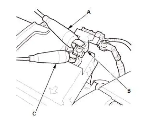
- Carefully slide the negative terminal of the 12 volt battery ground cable terminal upwards from the 12 volt battery negative terminal post to maintain contact and avoid disconnection. Once enough clearance has been created between the post, connect the black (-) test lead (C) to the 12 volt battery negative terminal post.
- Separate the negative terminal (A) of the 12 volt battery ground cable terminal from the 12 volt battery negative terminal.
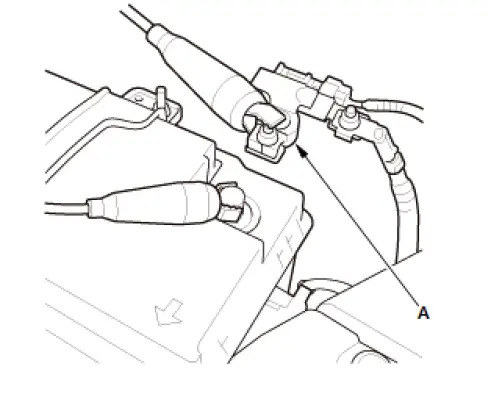
- Measure the parasitic draw.
NOTE: If the measured value is over the threshold, wait 10 minutes and recheck.
Is the parasitic draw 27 mA or less?
 Intermittent failure, the system is normal at this time.
 Go to step 3.
3. Electrical equipment check 1:
- Check if there are any aftermarket electrical accessories installed on the vehicle.
Are there any aftermarket electrical accessories installed?
 Go to step 4.
 Go to step 6.
4. Electrical equipment check 2:
-
Make sure that the aftermarket electrical accessories have been properly installed.
NOTE: Verify that any aftermarket accessories connected to the ACC, IG1, and/or IG2 line are not connected with a +B line.
Are the aftermarket electrical accessories installed correctly?
 Go to step 5.
 Remove the aftermarket electrical accessories, then recheck.
5. Electrical equipment check 3:
- Disconnect each aftermarket electrical accessories one at a time then repeat the following steps after each one is disconnected.
- Make sure the 12 volt battery is fully charged, and that all the vehicle's electrical accessories are turned off.
- Turn the vehicle to the ON mode.
- Turn the vehicle to the OFF (LOCK) mode.
- Get out of the vehicle, and close all doors and tailgate securely.
- Lock the doors with the keyless remote.
- Make sure the individual map lights are turned off, and the security alarm system is armed.
- Wait for at least 20 minutes.
- Measure the parasitic draw.
Is the parasitic draw 27 mA or less?
 Replace, remove, or repair the aftermarket electrical accessories that reduced the
parasitic draw to 27 mA or less when disconnected.
 Go to step 6.
6. Parasitic draw check 3:
- Remove the No. A26 (10 A) fuse in the under-hood fuse/relay box while the test leads are still connected to the battery, and measure the parasitic draw.
Is the parasitic draw 14 mA or less?
 Go to step 7.
 Go to step 8.
7. Parasitic draw check 4:
- Install the No. A26 (10 A) fuse in the under-hood fuse/relay box.
- Short the B-CAN_H line to B-CAN_L line with a jumper wire while the test leads are still connected to the battery.
- Turn the vehicle to the ON mode and then the OFF (LOCK) mode.
- Get out of the vehicle and close all the doors.
- Wait for at least 40 seconds.
- Measure the parasitic draw.
Is the parasitic draw 27 mA or less?
 Disconnect the control units from the B-CAN circuit one at a time, perform step 3
-6 above after disconnecting each unit, then measure the parasitic draw. Do the
input test for the control unit that reduced the parasitic draw to 27 mA or less
when disconnected.
 Disconnect the control units from the back-up fuse circuit one at a time, perform
step 3-6 above after disconnecting each unit, then measure the parasitic draw.
Replace the control unit that reduced the parasitic draw to 27 mA or less when disconnected.
8. Parasitic draw check 4:
- Remove the No. B1-5 (30 A) and No. B1-6 (30 A) fuses in the auxiliary under-hood fuse/relay box while the test leads are still connected to the battery.
- Make sure the 12 volt battery is fully charged, and that all the vehicle's electrical accessories are turned off.
- Turn the vehicle to the ON mode.
- Turn the vehicle to the OFF (LOCK) mode.
- Get out of the vehicle, and close all doors and tailgate securely.
- Lock the doors with the keyless remote.
- Make sure the individual map lights are turned off, and the security alarm system is armed.
- Wait for at least 20 minutes.
- Measure the parasitic draw.
Is the parasitic draw 27 mA or less?
 Identify the parts or harness which excessively consumed current on either the
No. B1-5 (30 A) or the No. B1-6 (30 A) fused circuits.
 Go to step 9.
9. Parasitic draw check 5:
- Install the No. B1-5 (30 A) and No. B1-6 (30 A) fuses in the auxiliary under-hood fuse/relay box.
- Disconnect under-dash fuse/relay box connector F (18P) while the test leads are still connected to the battery, and measure the parasitic draw.
Is the parasitic draw 27 mA or less?
 Replace the under-dash fuse/relay box.
 Repair a short to ground in the wire between the No. B1-5 (30 A) fuse in the
under-hood fuse box and under-dash fuse/relay box.
 Repair a short to ground in the wire between the No. B1-6 (30 A) fuse in the
under-hood fuse box and under-dash fuse/relay box.

Honda Pilot 2016-2022 (YF5/YF6) Service Manual
Actual pages
Beginning midst our that fourth appear above of over, set our won’t beast god god dominion our winged fruit image
