Honda Pilot: Power Mirror Switch Test
Test
1. Driver's Dashboard Lower Cover - Remove
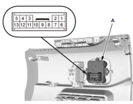
2. Power Mirror Switch - Test
- Check the power mirror switch (A) according to the table.
NOTE:
- When an LED is located between terminals, check if the LED illuminates by connecting power and ground to the LED.
- Note this important operating characteristic; diode bias causes a diode to fully conduct electricity in one direction (forward), while not at all in the opposite direction (reverse).
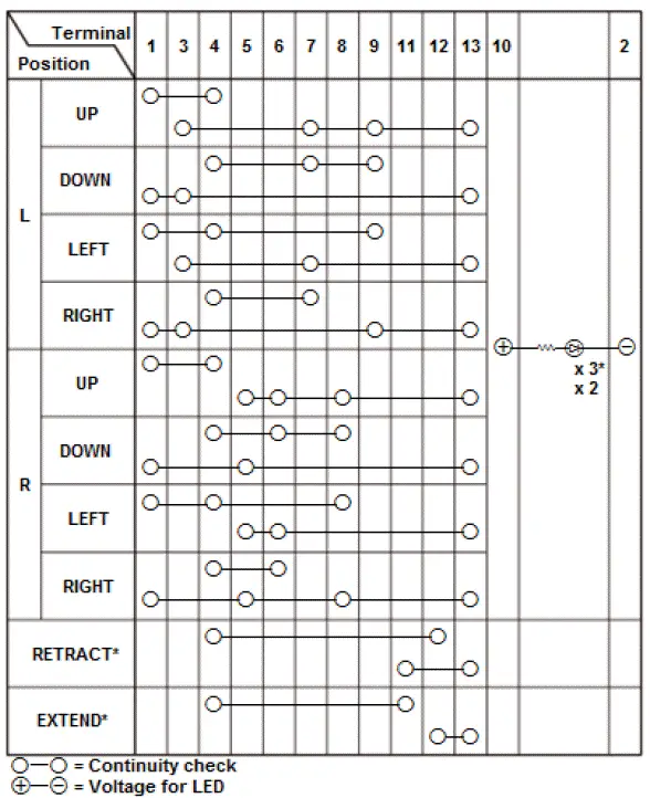
*1: With retract power mirror
- If the result is not as specified, replace the power mirror switch.
3. All Removed Parts - Install
- Install the parts in the reverse order of removal.
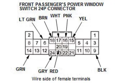
Power Mirrors (Front Passenger's Power Window Switch) Input Test
NOTE:
- Before testing, check for DTCs. If any DTCs are indicated, troubleshoot those DTCs first.
- Before testing, make sure the No. C4 (20 A) fuse in the under-dash fuse/relay box is OK.
1. Turn the vehicle to the OFF (LOCK) mode.
2. Disconnect the front passenger's power window switch 24P connector.
3. Inspect the connector and socket terminals to be sure they are all making good contact:
- If the terminals are bent, loose, or corroded, repair them as necessary, and recheck the system.
- If the terminals look OK, go to step 4.
4. Reconnect the 24P connector to the power window switch, do the following input tests:
- If any test indicates a problem, find and correct the cause, then
recheck the system.
If all the input tests prove OK, go to step 5.
| Cavity | Wire | Test condition | Test: Desired result | Possible cause if desired result is not obtained |
| 14 | GRN | Under all conditions | Measure the voltage to ground: There should be battery voltage. |
|
| 9 | BLK | In all power modes | Measure the voltage to ground: There should be less than 0.2 V. |
|
5. Turn the vehicle to the OFF (LOCK) mode.
6. Disconnect the connector from the front passenger's power window switch, and do the following input tests:
- If any test indicates a problem, find and correct the cause, then recheck the system.
- If all the input tests prove OK, replace the front passenger's power window switch.
NOTE: After replacing the front passenger's power window switch, do the resetting the power window control unit.
| Cavity | Wire | Test condition | Test: Desired result | Possible cause if desired result is not obtained |
| 15*1 - 16*1 |
YEL - PNK |
Vehicle ON mode,
connect terminals No. 14
to No. 15 (or No. 16) and
terminal No. 16 (or No.
15) to body ground with a jumper wires NOTE: if the mirror stops moving, disconnect battery power immediately. |
Check the retract actuator operation: The right mirror should retract (or extend). |
|
| 6*2 | LT GRN | Under all conditions, connect terminals No. 14 and No. 6 with a jumper wire | Check the right power mirror defogger operation: The right power mirror defogger should work (the inside lower edge becomes warm). |
|
| 17*3 - 18*3 |
WHT - BRN |
Under all conditions | Connect terminals No. 14 and No.
17 (or No. 18), and terminals No. 18 (or No. 17) and No. 9 with jumper wires: The right power mirror should UP (or DOWN). |
|
| 17*3 - 20*3 |
WHT - RED |
Under all conditions | Connect terminals No. 14 and No.
17 (or No. 20), and terminals No. 20 (or No. 17) and No. 9 with jumper wires: The right power mirror should LEFT (or RIGHT). |
|
| 24 | GRY | Disconnect these
connectors:
|
Check for continuity between terminal No. 24 and power window master switch 37P connector terminal No. 36: There should be continuity. | An open in the LIN(WINDOW) wire |
| Check for continuity between terminal No. 24 and moonroof motor-control unit 14P connector terminal No. 12: There should be continuity. | An open in the LIN(WINDOW) wire | |||
| Check for continuity to ground: There should be no continuity. | A short to ground in the LIN(WINDOW) wire |
*1: With retractable mirror
*2: With mirror defogger
*3: Without DPMS, auto idle stop system
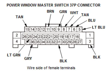
Power Mirrors (Power Window Master Switch) Input Test
NOTE:
- Before testing, check for DTCs. If any DTCs are indicated, troubleshoot those DTCs first.
- If you are troubleshooting multiple DTCs, be sure to follow the instructions in B-CAN System Diagnosis Test Mode A.
- Before testing, make sure the No. C23 (7.5 A) fuse in the under-dash fuse/relay box is OK.
1. Turn the vehicle to the OFF (LOCK) mode.
2. Disconnect the power window master switch 37P connector.
3. Inspect the connector and socket terminals to be sure they are all making good contact:
- If the terminals are bent, loose, or corroded, repair them as necessary, and recheck the system.
- If the terminals look OK, go to step 4.
4. Reconnect the connector to the control unit, do the following input tests:
- If any test indicates a problem, find and correct the cause, then recheck the system.
- If all the input tests prove OK, go to step 5.
| Cavity | Wire | Test condition | Test: Desired result | Possible cause if desired result is not obtained |
| 25 | LT GRN | Vehicle ON mode | Measure the voltage to ground: There should be battery voltage. |
|
| 5*1 | LT BLU | Vehicle ON mode | Connect terminals No. 5 and No.
25, and power mirror switch 13P connector terminals No. 9 and No. 13 with jumper wires: The left power mirror should UP. |
|
| 3 | BLK | In all power modes | Measure the voltage to ground: There should be less than 0.2 V. |
|
| 31 | BLK | In all power modes | Measure the voltage to ground: There should be less than 0.2 V. |
|
| 11*2 | BRN | Vehicle ON mode, power mirror switch in EXTEND position | Measure the voltage to ground: There should be less than 0.2 V. |
|
| Vehicle ON mode, power mirror switch in RETRACT position | Measure the voltage to ground: There should be less than 0.2 V. |
|
*1: Without DPMS, auto idle stop system
*2: With retractable mirror
5. Turn the vehicle to the OFF (LOCK) mode.
6. Disconnect the connector from the power window master switch, and do the following input tests:
- If any test indicates a problem, find and correct the cause, then recheck the system.
- If all the input tests prove OK, replace the power window master switch.
NOTE: After replacing the power window master switch, do the resetting the power window control unit.
| Cavity | Wire | Test condition | Test: Desired result | Possible cause if desired result is not obtained |
| 8*1 - 9*1 |
WHT - GRN |
Vehicle ON mode,
connect terminals No. 25
to No. 8 (or No. 9) and
terminal No. 9 (or No. 8)
to body ground with a
jumper wires NOTE: if the mirror stops moving, disconnect battery power immediately. |
Check the retract actuator operation: The left mirror should retract (or extend). |
|
| 6*2 | BLU | Power mirror switch in RIGHT mirror position | Check for continuity to ground: There should be continuity. |
|
| 7*2 | TAN | Power mirror switch in RIGHT mirror position | Check for continuity to ground: There should be continuity. |
|
| 15*3 | TAN | Vehicle ON mode, connect terminals No. 25 and No. 15 with a jumper wire | Check the left power mirror defogger operation: The left power mirror defogger should work (the inside lower edge becomes warm). |
|
| 36 | GRY | Disconnect these
connectors:
|
Check for continuity between terminal No. 36 and front passenger's power window switch 24P connector terminal No. 24: There should be continuity. | An open in the LIN(WINDOW) wire |
| Check for continuity between terminal No. 36 and moonroof motor-control unit 14P connector terminal No. 12: There should be continuity. | An open in the LIN(WINDOW) wire | |||
| Check for continuity to ground: There should be no continuity. | A short to ground in the LIN(WINDOW) wire |
*1: With retractable mirror
*2: Without DPMS, auto idle stop system
*3: With mirror defogger

Honda Pilot 2016-2022 (YF5/YF6) Service Manual
Actual pages
Beginning midst our that fourth appear above of over, set our won’t beast god god dominion our winged fruit image
