Honda Pilot: Power Tailgate Closer Motor Test
Honda Pilot 2016-2022 (YF5/YF6) Service Manual / Parts Test Info / Power Tailgate Closer Motor Test
Test
1. Tailgate Lower Trim Panel - Remove
2. Power Tailgate Closer Motor - Test
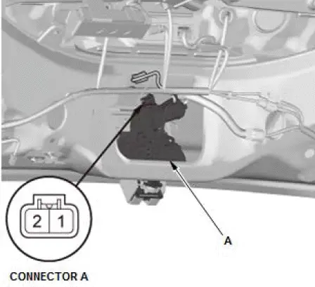
- Disconnect the connector A.
- Test the motor operation by connecting battery power to the tailgate closer unit connector A terminal No. 2 and ground to the terminal No. 1. To prevent damage to the motor, apply battery voltage only momentarily. The motor should run.
- If the motor does not run or fails to run smoothly, the power tailgate closer motor is faulty; replace the tailgate latch assembly (A).
3. All Removed Parts - Install
- Install the parts in the reverse order of removal.
Power Tailgate Control Unit Input Test
NOTE:
- Before testing, check for DTCs. If any DTCs are indicated, troubleshoot those DTCs first.
- If you are troubleshooting multiple DTCs, be sure to follow the instructions in B-CAN System Diagnosis Test Mode A.
- Before testing, make sure the No. A26 (10 A) fuse in the under-hood fuse/relay box is OK.
- Before testing, make sure the No. C28 (10 A) fuse in the under-dash fuse/relay box is OK.
- Before testing, make sure the No. B1-4 (40 A) and No. B6 (20 A) fuses in the auxiliary under-hood fuse/relay box are OK.
1. Turn the vehicle to the OFF (LOCK) mode.
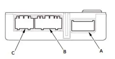
2. Disconnect the power tailgate control unit connectors.
NOTE: All connector views are shown from the wire side of the female terminals.
3. Inspect the connectors and socket terminals to be sure they are all making good contact:
- If the terminals are bent, loose, or corroded, repair them as necessary, and recheck the system.
- If the terminals are OK, go to step 4.
4. Reconnect the connectors, and do the following input tests:
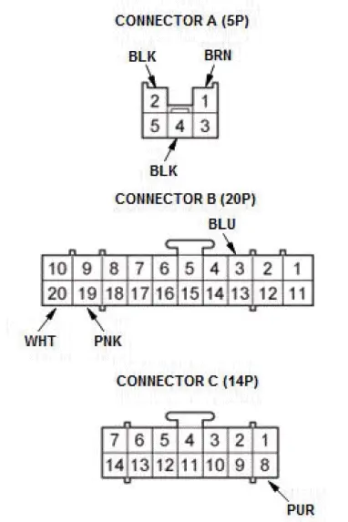
| Cavity | Wire | Test condition | Test: Desired result | Possible cause if desired result is not obtained |
| A1 | BRN | Under all conditions | Measure the voltage to ground: There should be battery voltage. |
|
| B19 | PNK | Under all conditions | Measure the voltage to ground: There should be battery voltage. |
|
| B20 | WHT | Under all conditions | Measure the voltage to ground: There should be battery voltage. |
|
| C8 | PUR | Power mode ON | Measure the voltage to ground: There should be battery voltage. |
|
| A2 | BLK | In all power modes | Measure the voltage to ground: There should be less than 0.2 V. |
|
| A4 | BLK | In all power modes | Measure the voltage to ground: There should be less than 0.2 V. |
|
| B3 | BLU | Shift position/mode in P | Measure the voltage to ground: There should be less than 0.2 V. |
|
| Shift position/mode in any position other than P | Measure the voltage to ground: There should be about 5 V. |
|
*1: 6-speed A/T
*2: 9-speed A/T

Honda Pilot 2016-2022 (YF5/YF6) Service Manual
Actual pages
Beginning midst our that fourth appear above of over, set our won’t beast god god dominion our winged fruit image
