Honda Pilot: Power Tailgate Pinch Sensor Test
Honda Pilot 2016-2022 (YF5/YF6) Service Manual / Parts Test Info / Power Tailgate Pinch Sensor Test
Test
1. Tailgate Lower Trim Panel - Remove
2. Power Tailgate Pinch Sensor - Test
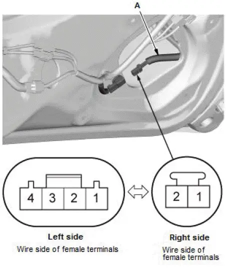
- Disconnect the connector.
- Measure the resistance between the pinch sensor connector terminals No. 1 and No. 2. The resistance value should be about 5 kΩ when the sensor is not pressed, and less than 2 kΩ when pressed.
- If the resistance is not as specified, replace the pinch sensor (A).
3. All Removed Parts - Install
- Install the parts in the reverse order of removal.
Power Window Master Switch Input Test
NOTE:
- Before testing, make sure the No. A26 (10 A) fuse in the under-hood fuse/relay box is OK.
- Before testing, make sure the No. C1 (7.5 A) fuses in the under-dash fuse/relay box are OK.
- Before testing, check for DTCs. If any DTCs are indicated, troubleshoot those DTCs first.
- If you are troubleshooting multiple DTCs, be sure to follow the instructions in B-CAN System Diagnosis Test Mode A.
1. Turn the vehicle to the OFF (LOCK) mode.
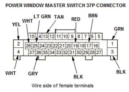
2. Disconnect the power window master switch 37P connector.
3. Inspect the connector and socket terminals to be sure they are all making good contact:
- If the terminals are bent, loose, or corroded, repair them as necessary, and recheck the system.
- If the terminals are OK, go to step 4.
4. With the connector still disconnected, do the following input tests:
- If any test indicates a problem, find and correct the cause, then recheck the system.
- If all the input tests prove OK, go to step 5.
| Cavity | Wire | Test condition | Test: Desired result | Possible cause if desired result is not obtained |
| 2 - 1 |
YEL - GRN |
Connect terminals No. 2 and No. 4, and terminals No. 1 and No. 3 with jumper wires. | Check driver's power window motor operation: The driver's power window should close. |
|
| Connect terminals No. 1 and No. 4, and terminals No. 2 and No. 3 with jumper wires. | Check driver's power window motor operation: The driver's power window should open. | |||
| 36 | GRY | Disconnect these
connectors:
|
Check for continuity between terminal No. 36 and front passenger's power window switch 24P connector terminal No. 24: There should be continuity. | An open in the LIN(P/W) wire |
| Check for continuity between terminal No. 36 and moonroof control unit/motor 14P connector terminal No. 12: There should be continuity. | An open in the LIN(P/W) wire | |||
| Check for continuity to ground: There should be no continuity. | A short to ground in the LIN(P/W) wire |
5. Reconnect the connector, and do the following input tests:
- If any test indicates a problem, find and correct the cause, then recheck the system.
- If all the input tests prove OK, replace the power window master switch.
NOTE: After replacing the power window master switch, do the resetting the power window control unit.
| Cavity | Wire | Test condition | Test: Desired result | Possible cause if desired result is not obtained |
| 4 | WHT | Under all conditions | Measure the voltage to ground: There should be battery voltage. |
|
| 26 | WHT | Under all conditions | Measure the voltage to ground: There should be battery voltage. |
|
| 25 | LT GRN | Vehicle ON mode | Measure the voltage to ground: There should be battery voltage. |
|
| 3 | BLK | In all power modes | Measure the voltage to ground: There should be less than 0.2 V. |
|
| 31 | BLK | In all power modes, disconnect the driver's power window motor 6P connector | Measure the voltage to ground: There should be less than 0.2 V. |
|
| 13 | TAN | Vehicle ON mode | Measure the voltage to ground: There should be battery voltage. |
|
| 17 | BRN | Vehicle ON mode, and driver's power window moving up or down | Measure the voltage between terminals No. 17 and No. 31: An analog meter should alternate between 0 V and 5 V (a digital voltmeter should read about 2.5 V while the window moves). |
|
| 19 | RED | Vehicle ON mode, and driver's power window moving up or down | Measure the voltage between terminals No. 19 and No. 31: An analog meter should alternate between 0 V and 5 V (a digital voltmeter should read about 2.5 V while the window moves). |
|

Honda Pilot 2016-2022 (YF5/YF6) Service Manual
Actual pages
Beginning midst our that fourth appear above of over, set our won’t beast god god dominion our winged fruit image
