Honda Pilot: Roof Console Module Test
Test
1. Roof Console Module - Remove
2. Roof Console Module - Test
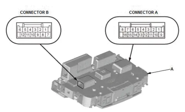
NOTE: The interior light switch and the individual map light switch are built into the roof console module (A).
- Check the interior light switch and the individual map light switch according to the table.
NOTE:
- When an LED is located between terminals, check if the LED lights by connecting power and ground to the LED.
- Note this important operating characteristic; diode bias causes a diode to fully conduct electricity in one direction (forward), while not at all in the opposite direction (reverse).
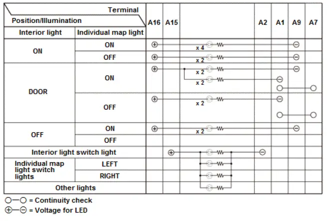
- If the result is not as specified, the interior light switch and/or the individual map light switch are faulty; replace the roof console module.
3. All Removed Parts - Install
- Install the parts in the reverse order of removal.
Safety Indicator System (MICU and Gauge Control Module) Input Test
NOTE:
- Before testing, troubleshoot the multiplex integrated control unit first, using B-CAN System Diagnosis Test Mode A.
- Before testing, do the gauge control module self-diagnostic function to make sure the beeper and the indicators in the gauge control module work properly and the F-CAN line are OK.
- Before testing, make sure the No. A26 (10 A) fuse in the under-hood fuse/relay box is OK.
- Before testing, make sure the No. B1-6 (30 A) fuse in the auxiliary under-hood fuse/relay box is OK.
- Before testing, make sure the No. C29 (7.5 A) fuse in the under-dash fuse/relay box is OK.
- With auto idle stop system: Before testing, make sure the No. D1 (7.5 A) fuse in the auxiliary under-dash fuse/relay box is OK.
MICU
1. Turn the vehicle to the OFF (LOCK) mode.
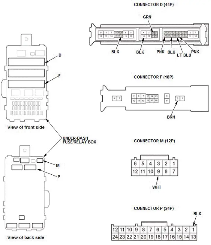
2. Disconnect under-dash fuse/relay box connectors D, F, M, and P.
NOTE: All connector views are shown from the wire side of the female terminals.
3. Inspect the connectors and socket terminals to be sure they are all making good contact:
- If the terminals are bent, loose, or corroded, repair them as necessary, and recheck the system.
- If the terminals are OK, go to step 4.
4. Reconnect the connectors to the under-dash fuse/relay box, and do the following input tests:
- If any test indicates a problem, find and correct the cause, then recheck the system.
- If all the input tests prove OK, go to step 5.
| Cavity | Wire | Test condition | Test: Desired result | Possible cause if desired result is not obtained |
| M9 | WHT | Under all conditions | Measure the voltage to ground: There should be battery voltage. |
|
| F2 | WHT | Vehicle ON mode | Measure the voltage to ground: There should be battery voltage. |
|
| D14 | BLK | In all power modes | Measure the voltage to ground: There should be less than 0.2 V. |
|
| D42 | BLK | In all power modes | Measure the voltage to ground: There should be less than 0.2 V. |
|
| P1 | BLK | In all power modes | Measure the voltage to ground: There should be less than 0.2 V. |
|
| D35 | LT BLU | Driver's door open | Measure the voltage to ground: There should be less than 0.2 V. |
|
| Driver's door closed | Measure the voltage to ground: There should be about battery voltage. |
|
||
| D37 | BLU | Front passenger's door open | Measure the voltage to ground: There should be less than 0.2 V. |
|
| Front passenger's door closed | Measure the voltage to ground: There should be about battery voltage. |
|
||
| D34 | PNK | Left rear door open | Measure the voltage to ground: There should be less than 0.2 V. |
|
| Left rear door closed | Measure the voltage to ground: There should be about battery voltage. |
|
||
| D28 | GRN | Right rear door open | Measure the voltage to ground: There should be less than 0.2 V. |
|
| Right rear door closed | Measure the voltage to ground: There should be about battery voltage. |
|
||
| D39 | PNK | Power tailgate closer unit connector B (6P) disconnected*1 | Check for continuity between terminal D39 and power tailgate closer unit connector B (6P) terminal No. 5: There should be continuity. | An open high resistance in the wire |
| Tailgate open*2 | Measure the voltage to ground: There should be less than 0.2 V. |
|
||
| Tailgate closed*2 | Measure the voltage to ground: There should be about battery voltage. |
|
*1: With power tailgate
*2: Without power tailgate
Gauge Control Module
5. Turn the vehicle to the OFF (LOCK) mode.
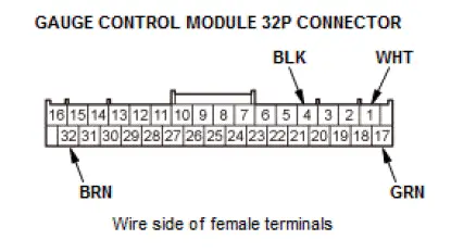
6. Disconnect the gauge control module 32P connector.
7. Inspect the connector and socket terminals to be sure they are all making good contact:
- If the terminals are bent, loose, or corroded, repair them as necessary, and recheck the system.
- If the terminals are OK, go to step 8.
8. Reconnect the connector, and do the following input tests:
- If any test indicates a problem, find and correct the cause, then recheck the system.
- If all the input tests prove OK, go to step 9.
| Cavity | Wire | Test condition | Test: Desired result | Possible cause if desired result is not obtained |
| 1 | WHT | Under all conditions | Measure the voltage to ground: There should be battery voltage. |
|
| 17 | GRN | Vehicle ON mode | Measure the voltage to ground: There should be battery voltage. |
|
| 4 | BLK | In all power modes | Measure the voltage to ground: There should be less than 0.2 V. |
|
| 32 | BRN | In all power modes | Measure the voltage to ground: There should be less than 0.2 V. |
|
*1: With auto idle stop system
*2: Without auto idle stop system
9. If multiple failures are found on more than one control unit, replace the under-dash fuse/relay box (includes the MICU). If input failures are related to a particular control unit, replace the gauge control module.

Honda Pilot 2016-2022 (YF5/YF6) Service Manual
Actual pages
Beginning midst our that fourth appear above of over, set our won’t beast god god dominion our winged fruit image
