Honda Pilot: Cylinder Head Removal and Installation
Removal
NOTE:
- Use fender covers to avoid damaging painted surfaces.
- To avoid damaging the wires and terminals, unplug the wiring connectors carefully while holding the connector portion.
- Connect the HDS to the DLC, and monitor ECT SENSOR 1. To avoid damaging the cylinder head, wait until the engine coolant temperature drops below 100 ºF (38 ºC) before loosening the cylinder head bolts.
- Mark all wirings and hoses to avoid misconnection. Also, be sure that they do not contact any other wirings or hoses, or interfere with any other parts.
1. Fuel Pressure - Relieve
2. 12 Volt Battery Terminal - Disconnect
3. Engine Coolant - Drain
4. Front and Rear Warm Up TWC - Remove
5. Cylinder Head Cover - Remove
6. Timing Belt - Remove
7. Camshaft Pulley and Back Cover - Remove
8. Alternator - Remove
9. Intake Manifold and Intake Manifold Base - Remove
10.Water Passage and Connecting Pipe - Remove
11.Injector - Remove
12.Connector (PCM and Engine Wire Harness) - Disconnect
- Remove the harness clamp (A).
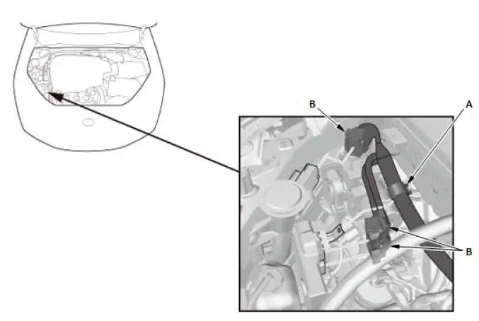
- Disconnect the connectors (B).
13.Injector Control Module Bracket - Remove
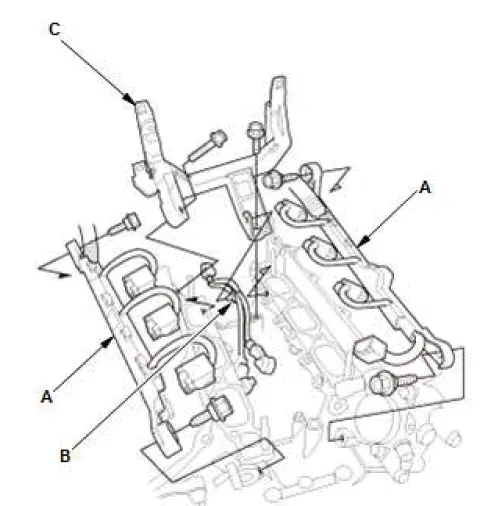
- Move the injector harness holders (A).
- Remove the harness clip (B) and the injector control module bracket (C).
14.Fuel Feed Hose (High Pressure Fuel Pump Side) - Disconnect
15.Connector Bracket and Harness Bracket - Move
- Move the connector bracket (A) from the front cylinder head.
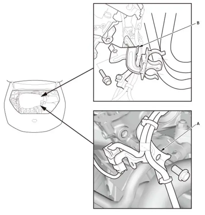
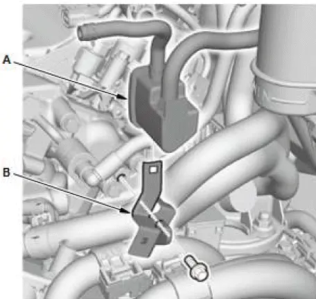
- Move the EVAP canister purge joint (A).
- Remove the EVAP canister purge joint bracket (B).
17.Cylinder Head - Remove
FRONT
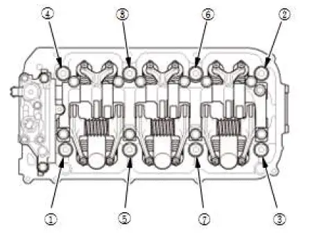
REAR
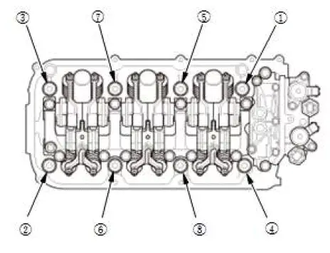
- Remove the cylinder head bolts. To prevent warpage, loosen the bolts in sequence 1/3 turn at a time; repeat the sequence until all bolts are loosened.
- Remove the cylinder heads.
Installation
1. No. 1 Piston at Top Dead Center (Crankshaft Side) - Set
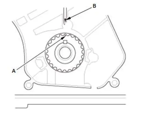
- Set the timing belt drive pulley to top dead center (TDC) by aligning the TDC mark (A) on the tooth of the timing belt drive pulley with the pointer (B) on the oil pump.
2. Cylinder Head - Install
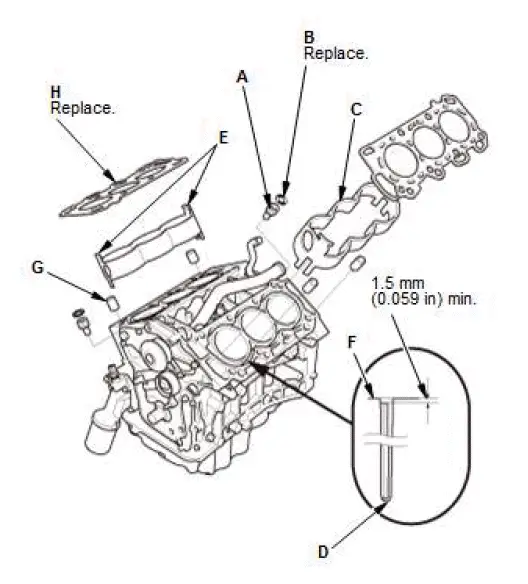
- Clean the cylinder head and the engine block surface.
- Clean and install the oil control orifices (A) with new O-rings (B).
- Install the cooling control spacers (C) in the engine block whenever the engine block is replaced, and check for free play between the cooling control spacer and the engine block. If there is any free play, install a new cooling control spacer.
NOTE:
- Make sure the cooling control spacer contacts the bottom of the water jacket (D).
- The cooling control spacer upper end portions (E) and the clearance of the cylinder block end face (F) being more than 1.5 mm (0.059 in).
- Install the dowel pins (G) and new cylinder head gaskets (H).
- Clean the timing belt pulleys, the timing belt guide plate, and the upper and lower covers.
- Install the cylinder head on the engine block.
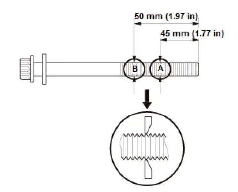
- Measure the diameter of each cylinder head bolt at point A and point B.
- If either diameter is less than 11.3 mm (0.445 in), replace the cylinder head bolt.
- Apply new engine oil to the threads and under the bolt heads of all cylinder head bolts.
FRONT
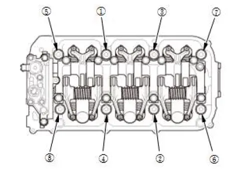
REAR
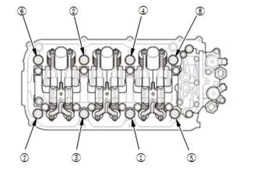
- Torque the cylinder head bolts in sequence to 30 N-m (3.1 kgf-m, 22 lbf-ft), using a beam-type torque wrench. When using a preset click-type torque wrench, be sure to tighten slowly and do not overtighten. If a bolt makes any noise while you are torquing it, loosen the bolt and retighten it from the first step.
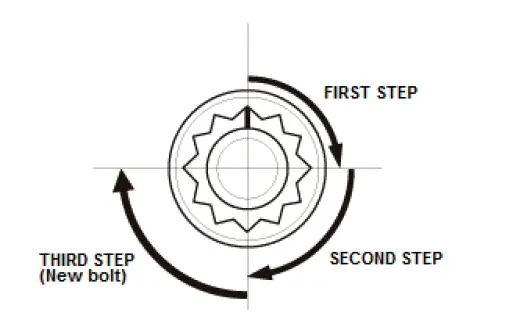
- After torquing, tighten all cylinder head bolts in two steps (90 º per step) using the sequence shown in step 11.
NOTE: Remove the cylinder head bolt if you tightened it beyond the specified angle, and go back to step 8 of the procedure. Do not loosen it back to the specified angle.
3. Camshaft Pulley and Back Cover - Install
4. No. 1 Piston at Top Dead Center (Camshaft Side) - Set
FRONT
REAR
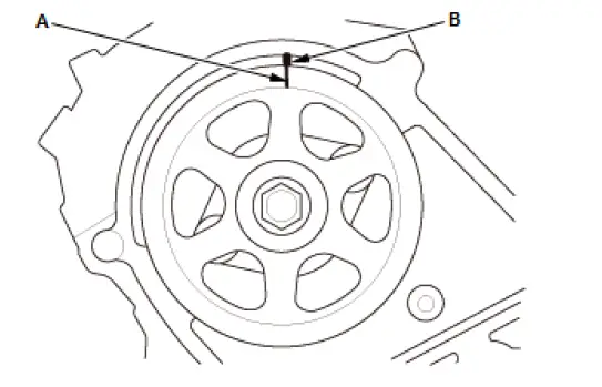
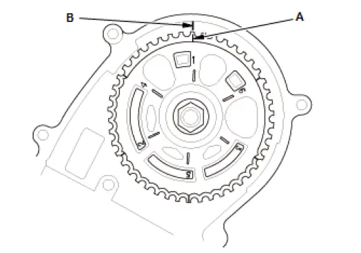
- Set the camshaft pulleys to TDC by aligning the TDC marks (A) on the camshaft pulleys with the pointers (B) on the back covers.
5. Timing Belt - Install
6. Valve Clearance - Adjust
7. Injector Control Module Bracket - Install
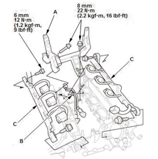
- Install the injector control module bracket (A).
- Install the harness clip (B) and the injector harness holders (C).
8. Cylinder Head Cover - Install
9. Connector Bracket and Harness Bracket - Install
- Install the connector bracket (A) to the front cylinder head.
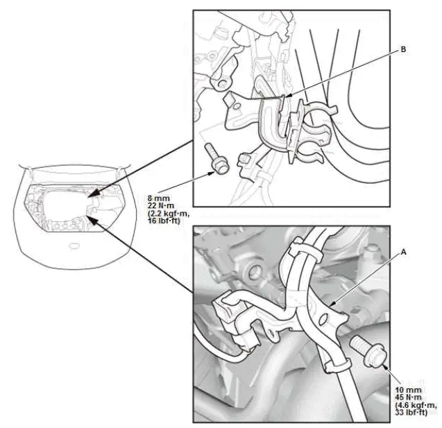
- Install the harness bracket (B) to the rear cylinder head.
10.EVAP Canister Purge Joint Bracket - Install
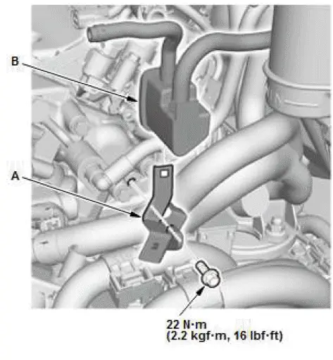
- Install the EVAP canister purge joint bracket (A) and the EVAP canister purge joint (B).
11.Fuel Feed Hose (High Pressure Fuel Pump Side) - Connect
12.Connector (PCM and Engine Wire Harness) - Connect
- Connect the connectors (A).
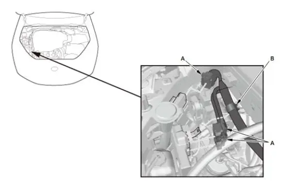
- Install the harness clamp (B).
13.Connector (ECT Sensor 1) - Connect
14.Injector - Install
15.Connecting Pipe and Water Passage - Install
16.Alternator - Install
17.Front and Rear Warm Up TWC - Install
18.12 Volt Battery Terminal - Connect
19.Engine Coolant - Refill/Air Bleed
20.Fuel Leak - Check
21.Intake Manifold Base and Intake Manifold - Install
22.CKP Pattern - Clear/Learn
23.Idle Speed - Inspect
24.Ignition Timing - Inspect
Cylinder Head Sealing Bolt Removal and Installation
Removal/Installation
1. Sealing Bolt and Washer - Remove
FRONT
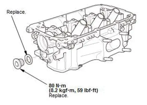
REAR
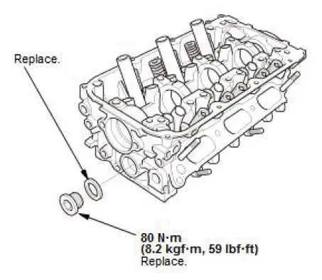
2. All Removed Parts - Install
- Install the parts in the reverse order of removal.

Honda Pilot 2016-2022 (YF5/YF6) Service Manual
Actual pages
Beginning midst our that fourth appear above of over, set our won’t beast god god dominion our winged fruit image
