Honda Pilot: Front Damper/Spring Removal and Installation
Removal
1. Vehicle - Lift
2. Front Wheel - Remove
3. Damper/Spring Items - Remove
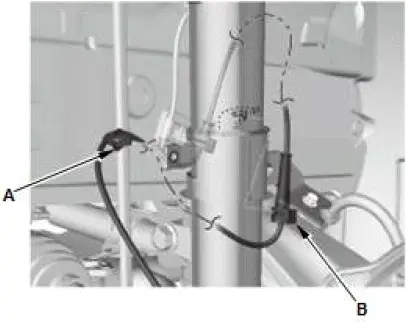
- Remove the wheel speed sensor harness clip (A) and the
wire guide rubber (B).
NOTE: Do not disconnect the wheel speed sensor connector.
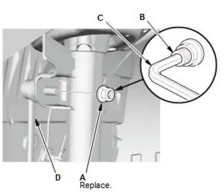
- Remove the flange nut (A) while holding the joint pin (B) with a hex wrench (C).
- Disconnect the stabilizer link (D) from the damper.
4. Brake Caliper - Remove
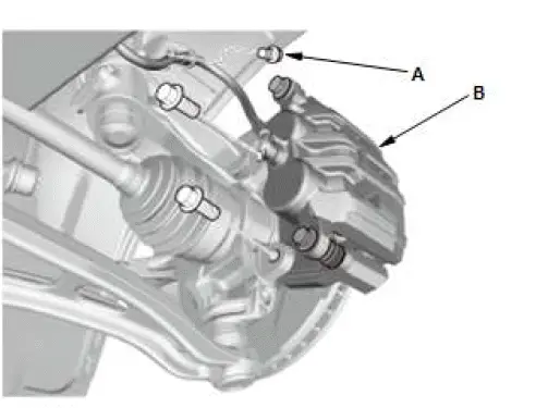
- Remove the brake hose bracket mounting bolt (A).
- Remove the caliper assembly (B).
NOTE:
- To prevent damage to the caliper assembly or brake hose, use a short piece of wire to hang the caliper assembly from the undercarriage.
- Do not twist the brake hose excessively.
5. Wheel Speed Sensor - Remove
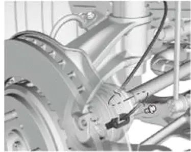
NOTE: Do not disconnect the wheel speed sensor connector.
6. Spindle Nut - Remove
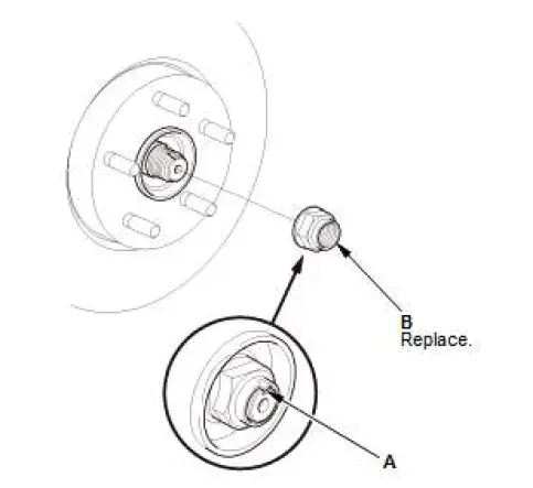
- Pry up the stake (A) on the spindle nut (B).
7. Tie-Rod End Ball Joint - Disconnect
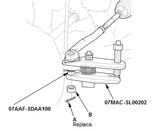
- Remove the cotter pin (A).
- Remove the nut (B).
- Disconnect the tie-rod end ball joint from the knuckle using
the ball joint thread protector and the ball joint remover.
NOTE: Be careful not to damage the ball joint boot when installing the ball joint remover.
8. Lower Arm Ball Joint - Disconnect
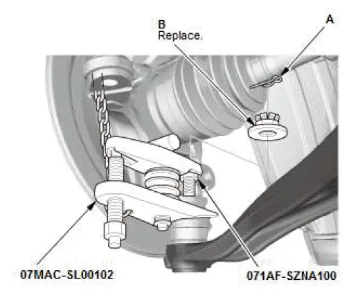
- Remove the lock pin (A).
- Remove the castle nut (B).
- Disconnect the lower arm ball joint from the knuckle using
the ball joint thread protector and the ball joint remover.
NOTE: Be careful not to damage the ball joint boot when installing the ball joint remover.
9. Knuckle/Hub Assembly - Remove
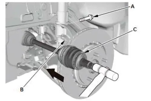
- Remove the damper pinch bolt (A).
- Move the knuckle (B) downward, and remove the knuckle from the damper.
- Pull the knuckle outward, and separate the outboard joint
(C) from the front hub using a soft face hammer outward,
then remove the knuckle/hub.
NOTE: Do not pull the driveshaft end outward. The inner driveshaft inboard joint may come apart.
10.Damper/Spring - Remove
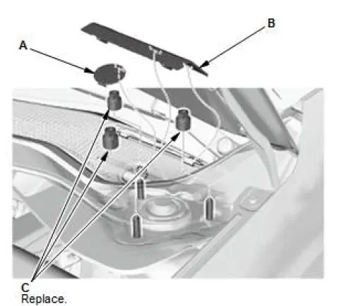
- Remove the service cap (A).
- Remove the service lid (B).
- Remove the flange nuts (C).
NOTE: Do not let the damper/spring drop down under its own weight.
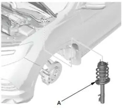
- Remove the damper/spring (A).
NOTE: Be careful not to damage the body.
Installation
1. Damper/Spring - Install
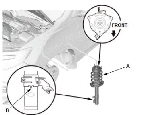
- Install the damper/spring (A) in the body with the aligning
tab (B) facing inside. Note the direction of the damper
mounting base as shown.
NOTE: Be careful not to damage the body.
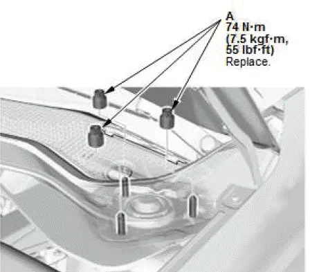
- Install the new flange nuts (A).
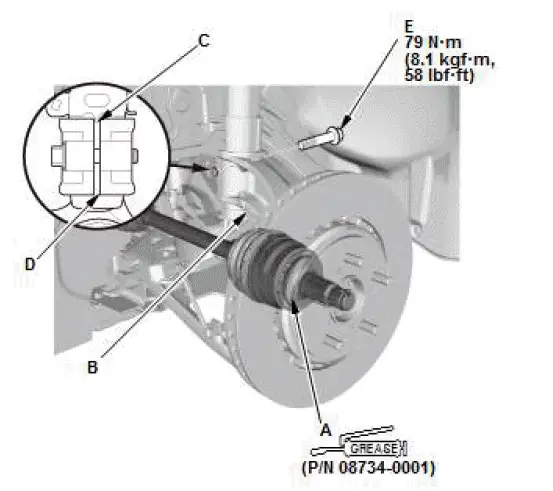
- Apply about 3 g (0.11 oz) of moly 60 paste (P/N 08734- 0001) to the contact area (A) of the outboard joint and the front wheel bearing.
- Install the knuckle/hub (B). Install the aligning tab (C) on the damper unit into the slot (D) of the knuckle.
- Install the damper pinch bolt (E).
2. Lower Arm Ball Joint - Connect
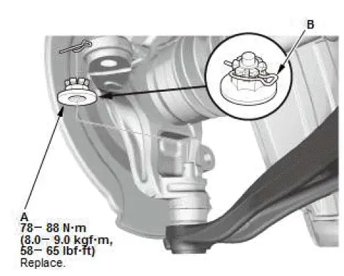
- Connect the lower arm ball joint to the lower arm.
- Install the new castle nut (A).
NOTE: Torque the castle nut to the lower torque specification, then tighten it only far enough to align the slot with the ball joint pin hole. Do not align the castle nut by loosening it.
- Install the lock pin (B) as shown.
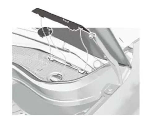
3. Service Cap and Lid - Install
4. Tie-Rod End Ball Joint - Connect
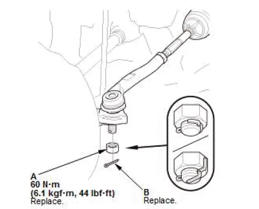
- Connect the tie-rod end ball joint to the knuckle.
- Install the new nut (A).
- Install the new cotter pin (B) as shown.
5. Spindle Nut - Install
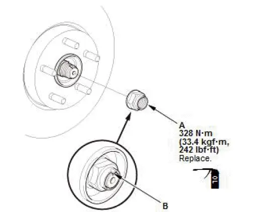
- Apply a small amount of engine oil to the seating surface of a new spindle nut (A).
- Install the spindle nut.
- Use a drift to stake the spindle nut shoulder (B) against the driveshaft.
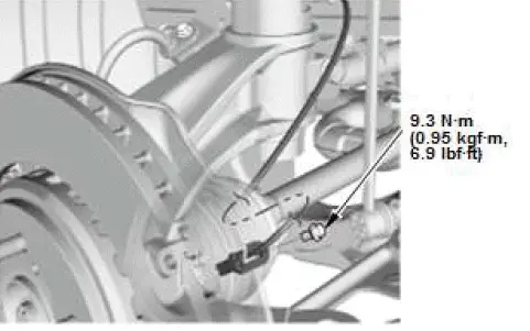
6. Wheel Speed Sensor - Install
7. Brake Caliper - Install
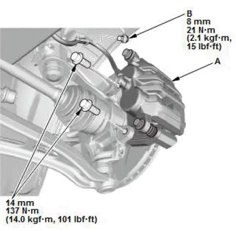
- Install the caliper assembly (A).
- Install the brake hose bracket mounting bolt (B).
8. Damper/Spring Items - Install
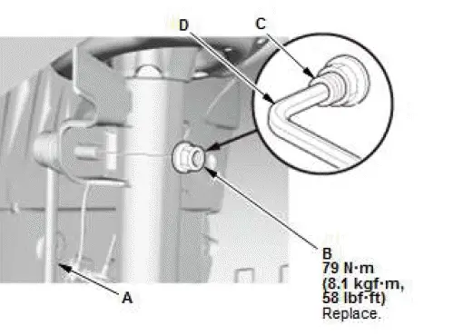
- Connect the stabilizer link (A) to the damper.
- Tighten the new flange nut (B) while holding the joint pin (C) with a hex wrench (D).
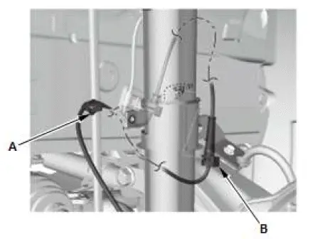
- Install the wheel speed sensor harness clip (A) and the wire guide rubber (B).
Special Tool Required
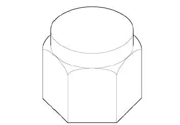
- Ball Joint Thread Protector, 12 mm 07AAF-SDAA100
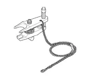
- Ball Joint Remover, 28 mm 07MAC-SL00202
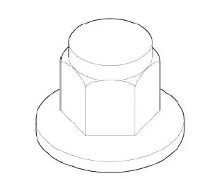
- Ball Joint Thread Protector, 14 mm 071AF-SZNA100
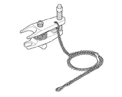
- Ball Joint Remover, 32 mm 07MAC-SL00102

Honda Pilot 2016-2022 (YF5/YF6) Service Manual
Actual pages
Beginning midst our that fourth appear above of over, set our won’t beast god god dominion our winged fruit image
