Honda Pilot: Fuel Pressure Test
Test
1. Fuel Pressure - Relieve
2. Fuel Pressure - Test
NOTE: If you were referred to this procedure from a troubleshooting procedure, test the fuel pressure under the same conditions the malfunction occurred (engine speed, load, throttle position, etc.).
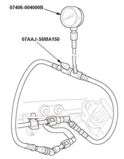
- Disconnect the quick-connect fitting and attach the fuel pressure gauge set. Check for leaks with the gauge set attached.
- Start the engine, and let it idle.
- If the engine starts, go to step 3 and read the fuel pressure gauge.
- If the pump does not run and any DTCs are stored, do the DTC troubleshooting.
- If the pump does not run and no DTCs are stored, do the fuel pump circuit troubleshooting.
- Read the fuel pressure gauge. The pressure should be: 410-460 kPa (4.18-4.69 kgf/cm2, 59.5-66.7 psi)
- If the pressure is OK, the test is complete.
- If the pressure is out of specification, replace the fuel pressure regulator and the fuel filter, then recheck the fuel pressure.
Gauge Control Module Input Test
NOTE:
- Before testing, do the gauge control module self-diagnostic function, and make sure the B-CAN communication lines are OK.
- If you are troubleshooting multiple DTCs, be sure to follow the instructions in B-CAN System Diagnosis Test Mode A.
- Before testing, make sure the No. A26 (10 A) fuse in the under-hood fuse/relay box is OK.
- With auto idle stop system: Before testing, make sure the No. D1 (7.5 A) fuse in the auxiliary under-dash fuse/relay box is OK.
- Without auto idle stop system: Before testing, make sure the No. C29 (7.5 A) fuse in the under-dash fuse/relay box is OK.
1. Turn the vehicle to the OFF (LOCK) mode.
2. Disconnect the gauge control module 32P connector.
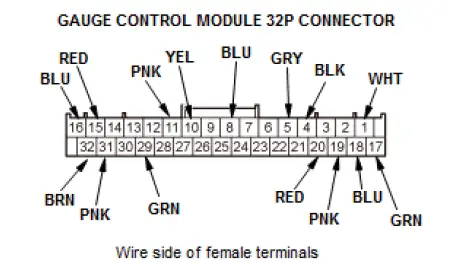
3. Inspect the connector and socket terminals to be sure they are all making good contact:
- If the terminals are bent, loose, or corroded, repair them as necessary, and recheck the system.
- If the terminals are OK, go to step 4.
4. With the connector still disconnected, do the following input tests:
- If any test indicates a problem, find and correct the cause, then recheck the system.
- If all the input tests prove OK, go to step 5.
| Cavity | Wire | Test condition | Test: Desired result | Possible cause if desired result is not obtained |
| 15 | RED | Combination light switch ON | Connect to ground with a jumper wire: The dashlights should come on full bright. |
|
| 16 | BLU | Combination light switch ON | Connect to ground with a jumper wire: The dashlights should come on full bright. |
|
| 10 | YELv | Parking brake pedal pressed | Check for continuity to ground: There should be continuity. |
|
| Parking brake pedal released | Check for continuity to ground: There should be no continuity. |
|
5. Reconnect the connector, and do the following input tests:
- If any test indicates a problem, find and correct the cause, then recheck the system.
- If all the input tests prove OK, replace the gauge control module.
| Cavity | Wire | Test condition | Test: Desired result | Possible cause if desired result is not obtained |
| 1 | WHT | Under all conditions | Measure the voltage to ground: There should be battery voltage. |
|
| 17 | GRN | Vehicle ON mode | Measure the voltage to ground: There should be battery voltage. |
|
| 4 | BLK | In all power modes | Measure the voltage to ground: There should be less than 0.2 V. |
|
| 32 | BRN | In all power modes | Measure the voltage to ground: There should be less than 0.2 V. |
|
| 11 | PNK | Vehicle ON mode, brake fluid is at full level in the reservoir | Measure the voltage to ground: There should be battery voltage. |
|
| Vehicle ON mode, brake fluid is at lower level in the reservoir | Measure the voltage to ground: There should be less than 0.2 V. |
|
||
| 31 | PNK | Vehicle ON mode, dashlights brightness control ILLUMI () button pushed | Measure the voltage to ground: There should be less than 0.2 V. |
|
| Vehicle ON mode, dashlights brightness control ILLUMI () button released | Measure the voltage to ground: There should be battery voltage. |
|
||
| 29 | GRN | Vehicle ON mode, dashlights brightness control ILLUMI (+) button pushed | Measure the voltage to ground: There should be less than 0.2 V. |
|
| Vehicle ON mode, dashlights brightness control ILLUMI (+) button released | Measure the voltage to ground: There should be battery voltage. |
|
||
| 8 | BLU | Vehicle ON mode, ECON switch ON | Measure the voltage to ground: There should be less than 0.2 V |
|
| Vehicle ON mode, ECON switch OFF | Measure the voltage to ground: There should be battery voltage. |
|
||
| 5 | GRY | Vehicle ON mode, washer fluid is half or more in the washer reservoir | Measure the voltage to ground: There should be battery voltage. |
|
| Vehicle ON mode, washer fluid is empty in the washer reservoir | Measure the voltage to ground: There should be less than 0.2 V. |
|
*1: With auto idle stop system
*2: Without auto idle stop system
Special Tool Required
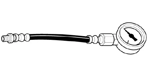
- Fuel Pressure Gauge 07406-004000B
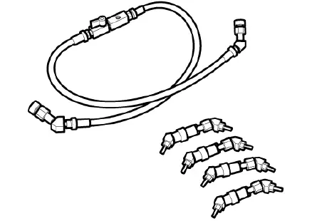
- Fuel Pressure Gauge Attachment Set 07AAJ-S6MA150

Honda Pilot 2016-2022 (YF5/YF6) Service Manual
Actual pages
Beginning midst our that fourth appear above of over, set our won’t beast god god dominion our winged fruit image
