Honda Pilot: Hazard Warning Switch Test
Test
1. Dashboard Center Panel - Remove
2. Hazard Warning Switch - Test
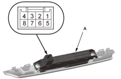
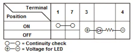
- Check for continuity between the terminals in each switch position according to the table.
NOTE:
- When an LED is located between terminals, check if the LED illuminates by connecting power and ground to the LED.
- Note this important operating characteristic; diode bias causes a diode to fully conduct electricity in one direction (forward), while not at all in the opposite direction (reverse).
- If the continuity is not as specified, replace the hazard warning switch (A).
3. All Removed Parts - Install
- Install the parts in the reverse order of removal.
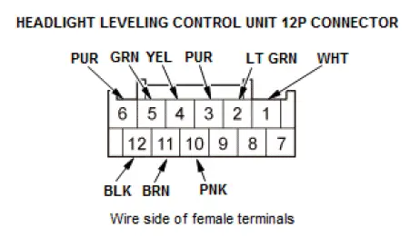
Headlight Leveling Control Unit Input Test
NOTE:
- Before testing, check for DTCs. If any DTCs are indicated, troubleshoot those DTCs first, and combination light switch circuit is OK.
- If you are troubleshooting multiple DTCs, be sure to follow the instructions in B-CAN System
- Diagnosis Test Mode A.
- Before testing, make sure the No. C28 (10 A) fuse in the under-dash subrelay box is OK.
1. Turn the vehicle to the OFF (LOCK) mode.
2. Disconnect the headlight leveling control unit 12P connector.
3. Inspect the connector and socket terminals to be sure they are all making good contact:
- If the terminals are bent, loose, or corroded, repair them as necessary, and recheck the system.
- If the terminals are OK, go to step 4.
4. Reconnect the connector, and do the following input tests:
- If any test indicates a problem, find and correct the cause, then recheck the system.
- If all the input tests prove OK, replace the headlight leveling control
unit.
NOTE: After replacing the headlight leveling control unit, do the headlight initial position learning procedure.
| Cavity | Wire | Test condition | Test: Desired result | Possible cause if desired result is not obtained |
| 6 | PUR | Vehicle ON mode | Measure the voltage to ground: There should be battery voltage. |
|
| 12 | BLK | In all power modes | Measure the voltage to ground: There should be less than 0.2 V. |
|
| 3 | PUR | Under all conditions | Check for continuity to ground: There should be continuity. |
|
| 4 | YEL | Under all conditions | Check for continuity to ground: There should be continuity. |
|
| 5 | GRN | Vehicle ON mode, and headlight switch ON | Measure the voltage between terminals No. 5 and No. 4: There should be about 5 V. |
|
| 4 | YEL | |||
| 11 | BRN | Vehicle ON mode, and headlight switch ON | Measure the voltage between the terminals No. 11 and No. 4: There should be about 0.5 to 4.5 V. |
|
| 4 | YEL | |||
| 2 | LT GRN | Vehicle ON mode, and headlight switch ON |
|
|
| 3 | PUR | |||
| 10 | PNK | |||
| 1 | WHT | Vehicle ON mode, and headlight switch ON |
|
|
| 3 | PUR | |||
| 10 | PNK |
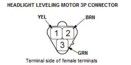
Headlight Leveling Motor Input Test
NOTE: Before testing, check for DTCs. If any DTCs are indicated, troubleshoot those DTCs first, and combination light switch circuit is OK.
1. Turn the vehicle to the OFF (LOCK) mode.
2. Disconnect the headlight leveling motor 3P connector.
3. Inspect the connector and socket terminals to be sure they are all making good contact:
- If the terminals are bent, loose, or corroded, repair them as necessary, and recheck the system.
- If the terminals are OK, go to step 4.
4. With the connector still disconnected, do the following input tests:
- If any test indicates a problem, find and correct the cause, then recheck the system.
- If all the input tests prove OK, replace the headlight leveling motor.
- Do the headlight leveling control unit input test.
| Cavity | Wire | Test condition | Test: Desired result | Possible cause if desired result is not obtained |
| 3 | GRN | Vehicle ON mode | Measure the voltage to ground: There should be battery voltage. |
|
| 1 | YEL | Under all conditions | Check for continuity to ground: There should be continuity. |
|
| 2 | BRN | Vehicle ON mode | Measure the voltage to ground: There should be about 0.5 to 4.5 V. |
|
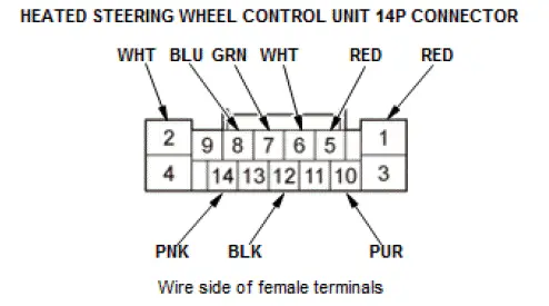
Heated Steering Wheel Control Unit Input Test
NOTE:
- If you are troubleshooting multiple DTCs, be sure to follow the instructions in B-CAN System Diagnosis Test Mode A.
- SRS components are located in this area. Review the SRS component locations, and precautions and procedures before doing repairs or servicing.
- Before testing, make sure the No. A27 (10 A) fuse in the under-hood fuse/relay box is OK.
- After testing, clear the SRS control unit DTCs.
1. Turn the vehicle to the OFF (LOCK) mode.
2. Do the 12 volt battery terminal disconnection procedure.
3. Remove the heated steering wheel control unit.
4. Inspect the connector and socket terminals to be sure they are all making good contact:
- If the terminals are bent, loose, or corroded, repair them as necessary, and recheck the system.
- If the terminals are OK, go to step 5.
5. With the connector still disconnected, do the following input tests:
- If any test indicates a problem, find and correct the cause, then recheck the system.
- If all the input tests prove OK, go to step 6.
| Cavity | Wire | Test condition | Test: Desired result | Possible cause if desired result is not obtained |
| 8 | BLU | Disconnect the gauge control module 32P connector and the 12 volt battery sensor 2P connector | Check for continuity between
terminal No. 8 and gauge control
module 32P connector terminal No.
23: There should be continuity. |
|
| Check for continuity to ground: There should be no continuity. |
|
|||
| 7 | GRN | Disconnect the steering heater 4P connector | Check for continuity between terminal No. 7 and steering heater 4P connector terminal No. 4: There should be continuity. | An open or high resistance in the wire |
6. Reconnect the connector, and do the following input tests:
- If any test indicates a problem, find and correct the cause, then recheck the system.
- If all the input tests prove OK, replace the heated steering wheel control unit.
| Cavity | Wire | Test condition | Test: Desired result | Possible cause if desired result is not obtained |
| 2 | WHT | Vehicle ON mode | Measure the voltage to ground: There should be battery voltage. |
|
| 12 | BLK | In all power modes | Measure the voltage to ground: There should be less than 0.2 V. |
|
| 1 | RED | Disconnect the steering heater 4P connector, vehicle ON mode, and heated steering switch ON | Measure the voltage to ground: There should be battery voltage. |
|
| 6 | WHT | Disconnect the steering heater 4P connector, vehicle ON mode, and heated steering switch ON | Measure the voltage to ground: There should be 5 V. |
|
| 5 - 14 |
RED - PNK |
Vehicle ON mode, and heated steering wheel button pressed | Measure the voltage between terminals No. 5 and No. 14: There should be less than 0.2 V. |
|
| Vehicle ON mode, and heated steering wheel button released | Measure the voltage between terminals No. 5 and No. 14: There should be battery voltage. |
|
||
| 10 | PUR | Vehicle ON mode | Connect to ground with a jumper wire: The heated steering wheel switch indicator should come on. |
|

Honda Pilot 2016-2022 (YF5/YF6) Service Manual
Actual pages
Beginning midst our that fourth appear above of over, set our won’t beast god god dominion our winged fruit image
