Honda Pilot: Park Pin Switch Test
Honda Pilot 2016-2022 (YF5/YF6) Service Manual / Parts Test Info / Park Pin Switch Test
Test
1. Center Console - Remove
2. Park Pin Switch - Test
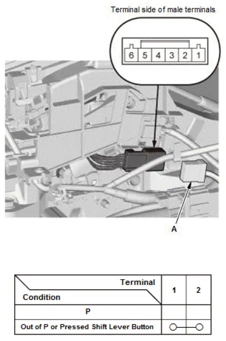
- Disconnect the connector (A).
- Check for continuity between the terminals in each shift lever condition according to the table.
- If the continuity is not as specified, check the shift cable adjustment. If the cable adjustment is OK, the park pin switch is faulty; replace the shift lock unit.
3. All Removed Parts - Install
- Install the parts in the reverse order of removal.
Parking and Back-Up Sensor Control Unit Input Test
NOTE:
- Before testing, check for DTCs. If any DTCs are indicated, troubleshoot those DTCs first.
- If you are troubleshooting multiple DTCs, be sure to follow the instructions in B-CAN System Diagnosis Test Mode A.
- Before testing, make sure the gauge control module self-diagnostic function to make sure the beeper in the gauge control module work properly, and communication line checks are OK.
- Before testing, make sure the No. C29 (7.5 A) fuse in the under-dash fuse/relay box is OK.
1. Turn the vehicle to the OFF (LOCK) mode.
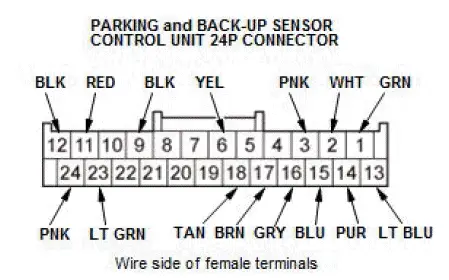
2. Disconnect the parking and back-up sensor control unit 24P connector.
3. Inspect the connector and socket terminals to be sure they are all making good contact:
- If the terminals are bent, loose, or corroded, repair them as necessary, and recheck the system.
- If the terminals are OK, go to step 4.
4. With the connector still disconnected, do the following input tests:
- If any test indicates a problem, find and correct the cause, then recheck the system.
- If all the input tests prove OK, go to step 5.
| Cavity | Wire | Test condition | Test: Desired result | Possible cause if desired result is not obtained |
| 24 | PNK | Vehicle ON mode, and parking and back-up sensor switch ON | Connect to ground with a jumper wire: The parking and back-up sensor switch indicator should come on. |
|
| 2 | WHT | Disconnect the right front corner sensor 6P connector | Check for continuity between terminal No. 2 and right front corner sensor 6P connector terminal No. 6: There should be continuity. | An open or high resistance in the wire |
| Check for continuity between the terminal No. 2 and body ground: There should be no continuity. | A short to ground in the wire | |||
| 11 | RED | Disconnect the right front corner sensor 6P connector | Check for continuity between terminal No. 11 and right front corner sensor 6P connector terminal No. 4: There should be continuity. | An open or high resistance in the wire |
| Check for continuity between the terminal No. 11 and body ground: There should be no continuity. | A short to ground in the wire | |||
| 3 | PNK | Disconnect the right front corner sensor 6P connector | Check for continuity between terminal No. 3 and right front corner sensor 6P connector terminal No. 2: There should be continuity. | An open or high resistance in the wire |
| Check for continuity between the terminal No. 3 and body ground: There should be no continuity. | A short to ground in the wire | |||
| 6 | YEL | Disconnect the left front corner sensor 6P connector | Check for continuity between terminal No. 6 and left front corner sensor 6P connector terminal No. 2: There should be continuity. | An open or high resistance in the wire |
| Check for continuity between the terminal No. 6 and body ground: There should be no continuity. | A short to ground in the wire | |||
| 14 | PUR | Disconnect the left rear corner sensor 6P connector | Check for continuity between terminal No. 14 and left rear corner sensor 6P connector terminal No. 6: There should be continuity. | An open or high resistance in the wire |
| Check for continuity between the terminal No. 14 and body ground: There should be no continuity. | A short to ground in the wire | |||
| 18 | TAN | Disconnect the left rear corner sensor 6P connector | Check for continuity between terminal No. 18 and left rear corner sensor 6P connector terminal No. 2: There should be continuity. | An open or high resistance in the wire |
| Check for continuity between the terminal No. 18 and body ground: There should be no continuity. | A short to ground in the wire | |||
| 23 | LT GRN | Disconnect the left rear corner sensor 6P connector | Check for continuity between terminal No. 23 and left rear corner sensor 6P connector terminal No. 4: There should be continuity. | An open or high resistance in the wire |
| Check for continuity between the terminal No. 23 and body ground: There should be no continuity. | A short to ground in the wire | |||
| 15 | BLU | Disconnect the right rear corner sensor 6P connector | Check for continuity between terminal No. 15 and right rear corner sensor 6P connector terminal No. 2: There should be continuity. | An open or high resistance in the wire |
| Check for continuity between the terminal No. 15 and body ground: There should be no continuity. | A short to ground in the wire | |||
| 16 | GRY | Disconnect the right rear center sensor 6P connector | Check for continuity between terminal No. 16 and right rear center sensor 6P connector terminal No. 2: There should be continuity. | An open or high resistance in the wire |
| Check for continuity between the terminal No. 16 and body ground: There should be no continuity. | A short to ground in the wire | |||
| 17 | BRN | Disconnect the left rear center sensor 6P connector | Check for continuity between terminal No. 17 and left rear center sensor 6P connector terminal No. 2: There should be continuity. | An open or high resistance in the wire |
| Check for continuity between the terminal No. 17 and body ground: There should be no continuity. | A short to ground in the wire |
5. Reconnect the connector, and do the following input tests:
- If any test indicates a problem, find and correct the cause, then recheck the system.
- If all the input tests prove OK, replace the parking and backup sensor control unit.
| Cavity | Wire | Test condition | Test: Desired result | Possible cause if desired result is not obtained |
| 1 | GRN | Vehicle ON mode | Measure the voltage to ground: There should be battery voltage. |
|
| 9 | BLK | In all power modes | Measure the voltage to ground: There should be less than 0.2 V. |
|
| 12 | BLK | In all power modes | Measure the voltage to ground: There should be less than 0.2 V. |
|
| 13 | LT BLU | Vehicle ON mode, and parking and back-up sensor switch ON | Measure the voltage to ground: There should be battery voltage. |
|

Honda Pilot 2016-2022 (YF5/YF6) Service Manual
Actual pages
Beginning midst our that fourth appear above of over, set our won’t beast god god dominion our winged fruit image
