Honda Pilot: Rear Differential System Description - i-VTM System
i-VTM System
Outline
This vehicle is equipped with a Intelligent-Variable Torque Management (i-VTM) rear differential system. This system uses wet multiple disc clutches and the i-VTM control unit to control front to rear torque distribution and independent left to right rear torque distribution.
The rear differential solenoid valves and the oil pump driven by the rear differential pump motor are built into the i-VTM hydraulic circuit. It achieves a wide range of torque control, responsibility improvement, downsizing, and weight reduction.
i-VTM features include:
- Independent torque distribution to the front and rear wheels and to the left and right wheels for neutral handling when cornering.
- Controls differential (inside/outside) wheel speed in a turn to increase cornering stability.
Operation
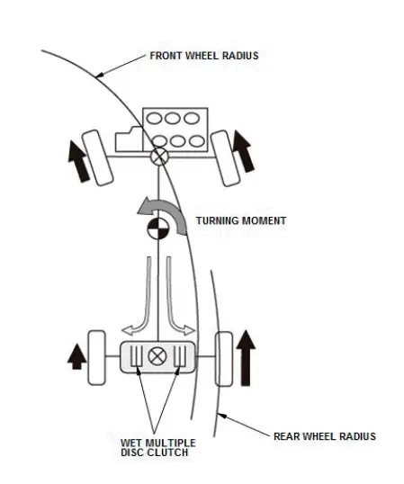
In a normal turn, the radius of the front wheels is shorter than the radius that the rear wheels travel. If the front and rear wheels are driven at the same speed, full power is not transmitted. The i-VTM system monitors the speed of the front wheels and increases the speed of the outside rear wheel proportionally around the larger radius. This improves stability and steering response. On slippery surfaces, this provides the improved traction of a 4-wheel drive system.
Power Transmission
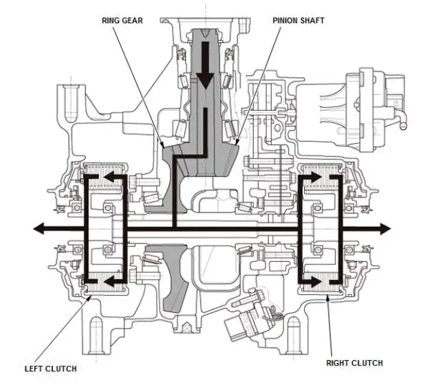
The sub carrier assembly contains the pinion shaft and the ring gear. Power flows through the sub carrier assembly providing power to the differential with a fixed 2.7 % acceleration ratio to the rear wheels. Power flows through the pinion shaft to the ring gear. If the clutches are disengaged, no power is transferred to the rear wheels. According to the driving condition, the driving power is transferred to the rear wheels by engaging or disengaging the left and right clutches. Because the clutch engaged condition of the left and right clutches is controlled separately, the driving power distribution to both clutches can be varied.
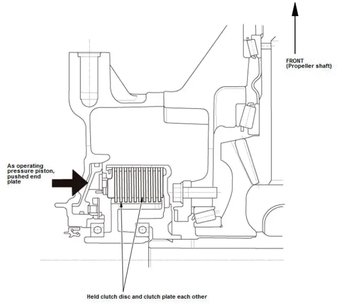
Driving force from the propeller shaft is transferred to both the clutch guide and clutch plate. As the i-VTM control unit closes the rear differential solenoid valves, the fluid from the oil pump to the clutch piston is pressurized. The end plate is pushed by the clutch piston so clutch discs and clutch plates are held to each other to engage the clutch.
Construction
The rear differential carrier assembly is composed of the wet multiple disc clutch and the hydraulic circuit.
Wet Multiple Disc Clutch
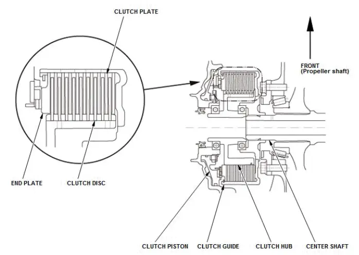
The wet multiple disc clutch components are shown below:
| Components | Contents |
| Clutch disc | Installed on clutch hub with spline |
| Clutch plate | Installed on clutch guide with spline |
| Clutch guide | Engaged to center shaft |
| Clutch hub | Engaged to rear driveshaft |
| Clutch piston | By hydraulic pressure, pushing end plate, then engaged clutch disc with clutch plate |
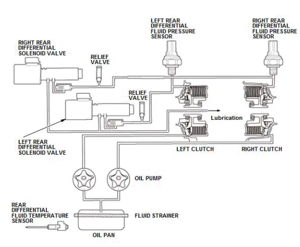
Hydraulic Circuit
The main components in the hydraulic circuit are shown below:
| Components | Contents |
| Oil pump | Driven by rear differential pump motor controlled by i-VTM control unit, delivering oil drawn up from fluid strainer to hydraulic circuit |
| Relief valve | Actuating when there is a fluid pressure malfunction, and releasing fluid pressure to the fluid strainer |
| Rear differential solenoid valve | Controlling fluid pressure to the clutch piston (Rear differential solenoid valves are normally open type (ON- CLOSE/OFF-OPEN), and are controlled by the electric current (duty controlled) from i-VTM control unit.) |
| Rear differential fluid pressure sensor | Detecting fluid pressure to each clutch, sending feedback signal to i- VTM control unit |
| Rear differential fluid temperature sensor | Detecting fluid temperature in hydraulic circuit, sending feedback signal to i-VTM control unit |
Hydraulic Pressure Control
The i-VTM control unit controls fluid pressure applied to the clutches by adjusting the opening amount of the left and right rear differential solenoid valves according to the driving condition.
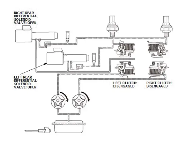
Vehicle Stop/Deceleration
Once the oil pump is driven by the rear differential pump motor, hydraulic pressure is generated and hydraulic pressure is applied to the clutches. Because the rear differential solenoid valves on the downstream of the clutches are OPEN (OFF), hydraulic pressure for the clutch piston does not rise so the clutches cannot be engaged.
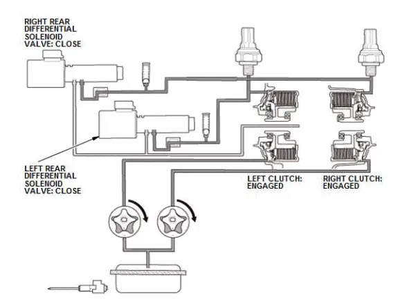
Acceleration
Once the oil pump is driven by the rear differential pump motor, hydraulic pressure is generated and hydraulic pressure is applied to the clutches. But because the rear differential solenoid valves on the downstream of the clutches are CLOSE (ON), hydraulic pressure for the clutch piston rises and the clutches can be engaged.
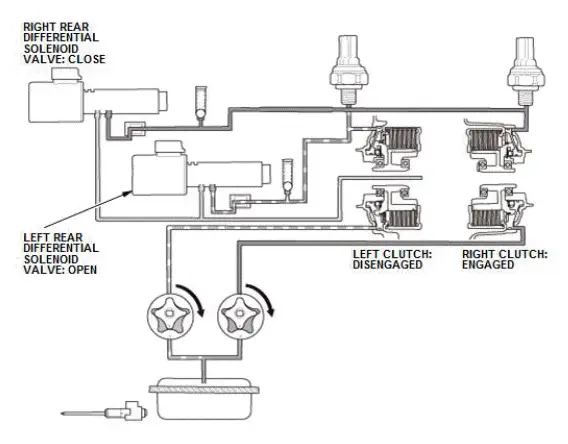
Left Turn
Left clutch: Once the oil pump is driven by the rear differential pump motor, hydraulic pressure is generated and hydraulic pressure is applied to the clutch. Because the rear differential solenoid valve on the downstream of the clutch is OPEN (OFF), hydraulic pressure for the clutch piston does not rise so the clutch cannot be engaged.
Right clutch: Once the oil pump is driven by the rear differential pump motor, hydraulic pressure is generated and hydraulic pressure is applied to the clutch. Because the rear differential solenoid valve on the downstream of the clutch is CLOSE (ON), hydraulic pressure for the clutch piston rises and the clutch can be engaged.
i-VTM System Operation Pattern Chart
i-VTM Control System
Control System
The i-VTM control system consists of the i-VTM control unit, PCM, TCM, yaw rate-acceleration sensor (VSA modulator-control unit), wheel speed sensor, gauge control module, and the steering angle sensor. The control units exchange information via the CAN communication lines. The i-VTM control unit has a self-diagnostic function. If a malfunction is detected, the i-VTM control unit turns on the AWD indicator in the gauge control module and the system goes into fail-safe mode. When in fail-safe mode, the vehicle disables the i-VTM differential. The vehicle defaults to front wheel drive and reduces engine torque to suit the driving conditions.
Driving Force Control
The driving force control distributes the power based on the driver's inputs. It distributes torque to the front and rear wheels based on the throttle opening and the available engine torque output. When turning, torque is applied to the rear wheels independently based on the lateral G input and the direction of the turn. This generates an inward yaw movement to help steer the vehicle around the turn.
Intelligent Traction Management (ITM)
The intelligent traction management switch can be pressed to activate the ITM system to suit specific terrain conditions. Once the switch is pressed, the i-VTM provides a smoother torque distribution according to the selected mode in addition to the regular torque control as shown below.

Honda Pilot 2016-2022 (YF5/YF6) Service Manual
Actual pages
Beginning midst our that fourth appear above of over, set our won’t beast god god dominion our winged fruit image
