Honda Pilot: Relay Circuit Board Removal, Installation, and Test
Removal/Installation
1. Relay Circuit Board - Remove
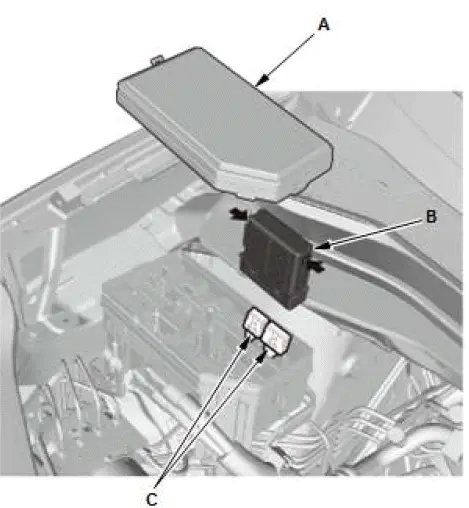
- Remove the cover (A).
- Remove the relay circuit board (B).
- Disconnect the connectors (C).
2. All Removed Parts - Install
- Install the parts in the reverse order of removal.
Test
1. Relay Circuit Board - Test
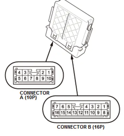
The relay circuit board is part of the under-hood fuse/relay box, and it contains these relay circuits:
- PGM-FI main relay 1 circuit
- Electronic throttle control system (ETCS) control relay circuit
- Ignition coil relay circuit
- PGM-FI subrelay circuit
- Windshield wiper intermittent relay circuit
- Windshield wiper high/low relay circuit
- Taillight relay circuit
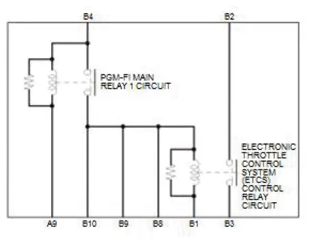
PGM-FI Main Relay 1 Circuit and Electronic Throttle Control System (ETCS) Control Relay Circuit
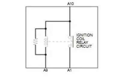
Ignition Coil Relay Circuit
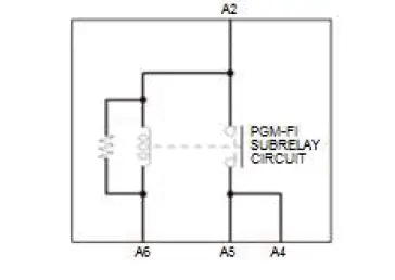
PGM-FI Subrelay Circuit
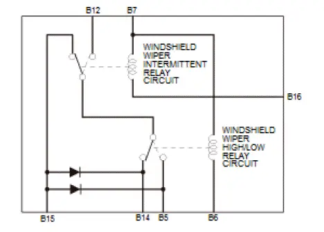
Windshield Wiper Intermittent Relay Circuit and Windshield Wiper High/Low Relay Circuit
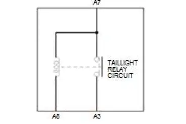
Taillight Relay Circuit
- Test each relay circuit as shown:
NOTE:
- Make sure the correct test lead (+or -) is placed on the terminal.
- When checking for continuity across the diode, use the
diode setting (
 ) on the digital volt/ohm meter to
check the diode bias.
) on the digital volt/ohm meter to
check the diode bias. - Note this important operating characteristic; diode bias causes a diode to fully conduct electricity in one direction (forward), while not at all in the opposite direction (reverse).
PGM-FI main relay 1 circuit
There should be battery voltage at terminals B10 (,B9, or B8) when 12 volt battery power is connected to terminal B4, and body ground is connected to terminal A9. There should be no voltage at terminals B10 (,B9, or B8) when terminal A9 is disconnected.
Electronic throttle control system (ETCS) control relay circuit
There should be continuity between terminals B2 and B3 when 12 volt battery power is connected to terminals B8 (,B9, or B10), and body ground is connected to terminal B1.
There should be no continuity between terminals B2 and B3 when terminal B8 is disconnected.
Ignition coil relay circuit
There should be battery voltage at terminal A1 when 12 volt battery power is connected to terminal A10, and body ground is connected to terminal A9. There should be no voltage at terminal A1 when terminal A9 is disconnected.
PGM-FI subrelay circuit
There should be battery voltage at terminals A4 and A5 when 12 volt battery power is connected to terminal A2, and body ground is connected to terminal A6. There should be no voltage at terminals A4 and A5 when terminal A6 is disconnected.
Windshield wiper intermittent relay circuit
There should be continuity between terminals B12 and B14 when 12 volt battery power is connected to terminal B7, and body ground is connected to terminal B16. There should be no continuity between terminals B12 and B14 when terminal B16 is disconnected.
Windshield wiper high/low relay circuit
There should be continuity between terminals B5 and B15 when 12 volt battery power is connected to terminal B7, and body ground is connected to terminal B6. There should be no continuity between terminals B5 and B15 when terminal B6 is disconnected.
Taillight relay circuit
There should be battery voltage at terminal A3 when 12 volt battery power is connected to terminal A7, and body ground is connected to terminal A8. There should be no voltage at terminal A3 when terminal A8 is disconnected.
- If any of these relay circuit fails the test, replace the relay circuit board.
RES Auxiliary Jack Assembly Removal and Installation
Removal/Installation
1. Center Console Rear Trim - Remove
2. A/C Power Outlet - Remove
3. USB Charger Unit - Remove
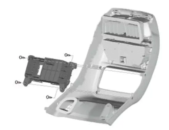
4. RES Auxiliary Jack Assembly - Remove
5. All Removed Parts - Install
- Install the parts in the reverse order of removal.

Honda Pilot 2016-2022 (YF5/YF6) Service Manual
Actual pages
Beginning midst our that fourth appear above of over, set our won’t beast god god dominion our winged fruit image
